Braking vane provided with rubber bumps and manufacture method of braking vane

A technology of rubber bumps and manufacturing methods, applied in the directions of brakes, brake components, vehicle parts, etc., can solve problems such as ineffective braking systems, vehicle stops, accidents, etc., to increase the sense of safety and driving confidence, and eliminate disadvantages. The psychological effect, the effect of convenient installation and replacement

Active Publication Date: 2016-04-20
胥荣欣
View PDF6 Cites 1 Cited by
  • Summary
  • Abstract
  • Description
  • Claims
  • Application Information

AI Technical Summary

Problems solved by technology

One of the major causes of traffic accidents is that the existing braking system of the vehicle is not effective enough. The existing braking system of the vehicle controls the driving of the vehicle by the limited friction generated by the contact between the tire and the ground, but due to the contact area between the tire and the ground Relatively small, the friction generated is not enough, so the vehicle cannot be stopped immediately, which greatly increases the probability of accidents
Taking an ordinary car as an example, assuming that the speed of the vehicle is 80mk / m, a pedestrian suddenly appears across the road ahead, the driver immediately takes braking measures, and the vehicle has to drive about 40m forward due to inertia to stop. If it is a heavy truck, Its inertia is greater, and the rushing distance is longer; and when driving in rainy days, snowy days, and icy roads, emergency braking usually causes a large uncontrollable slip, causing unimaginable dangers; in passenger and freight transportation In work, the performance of the braking system of the vehicle is directly related to the safety of human life and property. There are countless accidents directly caused by the failure of the braking system, especially on the long downhill section of the mountain road, due to the fatigue of the driver or improper operation, the brake pads are heated Carbonization leading to brake failure is also a common problem

Method used


Image

  • Braking vane provided with rubber bumps and manufacture method of braking vane
  • Braking vane provided with rubber bumps and manufacture method of braking vane
  • Braking vane provided with rubber bumps and manufacture method of braking vane

Examples


Embodiment 1

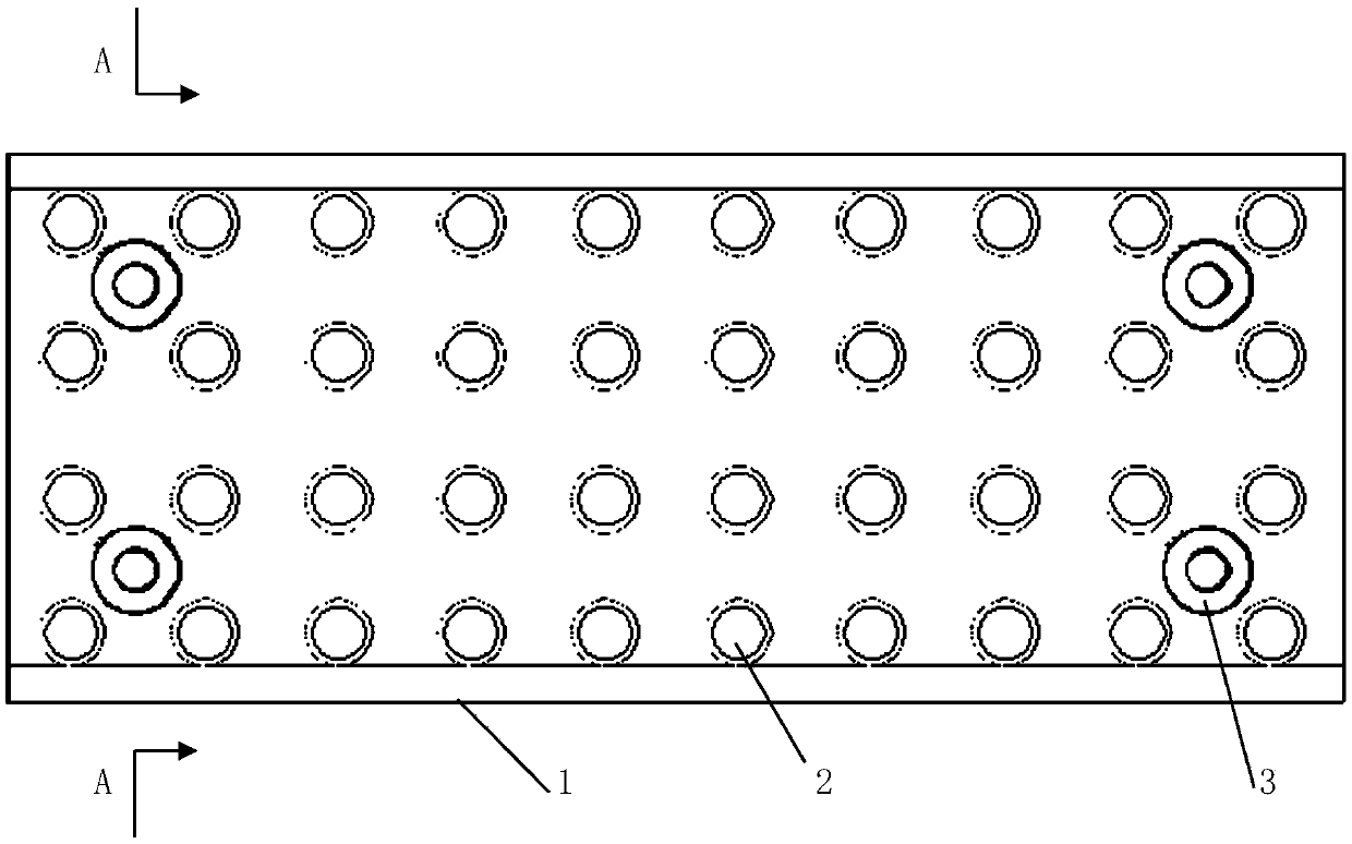
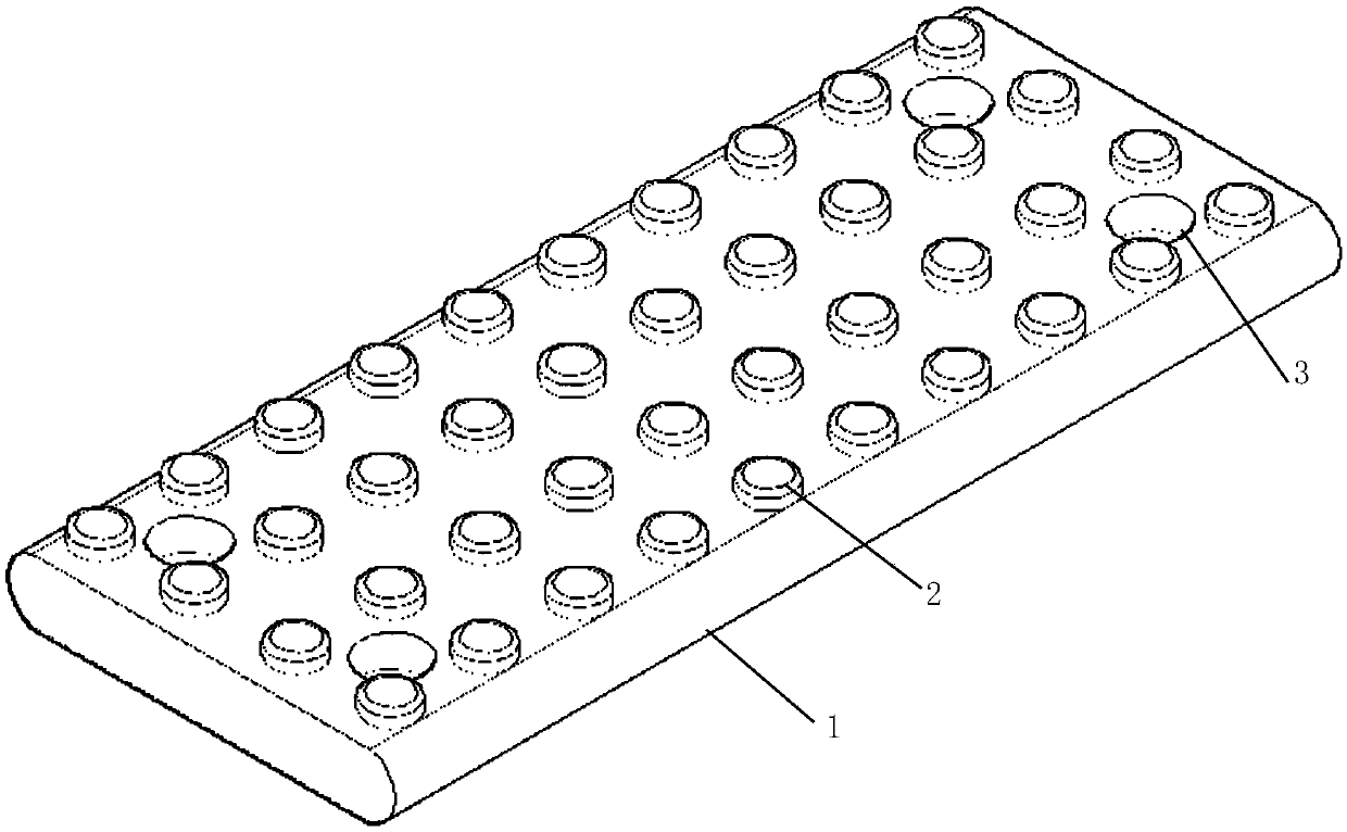
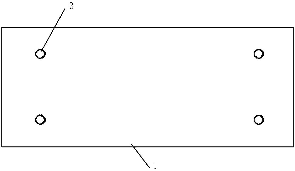
[0027] Embodiment 1: refer to attached Figure 1-6 , a brake pad 1 with rubber bumps of the present invention includes a board body, and is characterized in that: a grid 4 is provided in the board body, rubber bumps 2 are arranged on the board body, and four corners of the board body are provided with There are screw holes 3 or buckle slots.

[0028] In a further preferred solution, the plate body is rectangular, the screw hole 3 is a countersunk hole, and the bolt 8 is connected to the brake plate fixing frame 7 through the screw hole 3, or connected to the brake plate fixing frame through a buckle slot.

[0029] In a further preferred solution, the rubber bumps 2 are evenly distributed on the surface of the board body, the diameter of the bumps 2 is 10-30mm, and the height is 10-20mm.

[0030] In a further preferred solution, the grid 4 is a criss-cross nylon fiber grid or steel wire grid.

[0031] This embodiment also discloses a method for manufacturing a brake pad with ...


PUM

PropertyMeasurementUnit
heightaaaaaaaaaa
diameteraaaaaaaaaa
diameteraaaaaaaaaa

Abstract

The invention relates to road transport vehicles, in particular to a braking vane provided with rubber bumps and a manufacture method of the braking vane. The braking vane comprises a vane body, wherein a criss-cross grid is arranged in the vane body, a plurality of bumps are arranged on the vane body, screw holes for fixing or clamping grooves are formed in four corners of the vane body, the braking vane is arranged at the bottom of a vehicle through a fixing frame by the aid of bolts or the clamping grooves and is operated to lift and drop through a hand brake rod, and a braking function is realized through resistance of friction between the rubber bumps of the braking vane and a pavement.

Description

technical field [0001] The invention relates to the field of road transportation vehicles, in particular to a vehicle brake plate with rubber bumps and a manufacturing method thereof. Background technique [0002] With the development of society, the number of highway passenger and cargo transport vehicles has increased, and more traffic accidents have occurred at the same time, causing huge losses of life and property. One of the major causes of traffic accidents is that the existing braking system of the vehicle is not effective enough. The existing braking system of the vehicle controls the driving of the vehicle by the limited friction generated by the contact between the tire and the ground, but due to the contact area between the tire and the ground Relatively small, the friction generated is not enough, so the vehicle cannot be stopped immediately, which greatly increases the probability of accidents. Taking an ordinary car as an example, assuming that the speed of t...

Claims


Application Information

Patent Timeline
Patent Type & Authority Applications(China)
IPC IPC(8): B60T1/14C08L23/22C08K3/04
CPCB60T1/14C08K3/04C08L23/22
Inventor 隆剑猛
Owner 胥荣欣
Why Eureka
Try Eureka