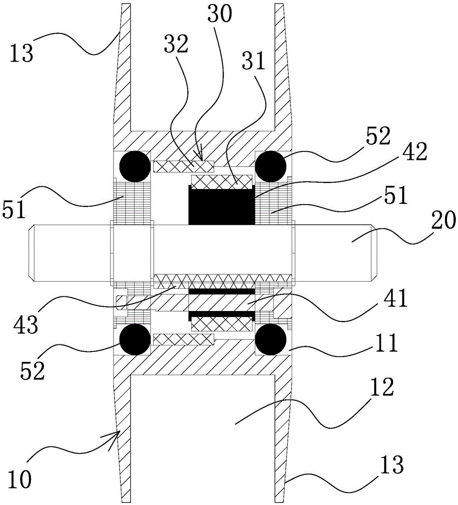
Magnetically-controlled wire unwinding spindle

A magnetic control technology, applied in the direction of conveying filamentous materials, thin material handling, transportation and packaging, etc., can solve the problems of uneven wire diameter, uneven force on the wire harness, loose and tight wire harness, etc. The overall structural design is reasonable, the production efficiency is high, and the force is uniform.

Inactive Publication Date: 2016-04-20
NINGBO LONG WALL FLUID KINETIC SCI TECH
View PDF6 Cites 4 Cited by
  • Summary
  • Abstract
  • Description
  • Claims
  • Application Information

AI Technical Summary

Problems solved by technology

[0003] The structure design of the existing pay-off spindle is unreasonable. It is equipped with a brake pad structure for releasing the tension inside, and it is supplemented by supports such as springs. Uneven tension between multiple pay-off spindles often leads to uneven stress on the wire harness during the pay-off process, resulting in uneven wire diameters, which in turn leads to loose and tight wire harnesses such as steel wires wound on rubber tubes, and poor work reliability.

Method used


Image

  • Magnetically-controlled wire unwinding spindle

Examples


Embodiment Construction

[0023] The following are specific embodiments of the present invention and in conjunction with the accompanying drawings, the technical solutions of the present invention are further described, but the present invention is not limited to these embodiments.

[0024] In the prior art, the structural design of the pay-off spindle is unreasonable. It is equipped with a brake pad structure for releasing the tension force inside, and is supplemented by supports such as springs. Uneven tension between multiple pay-off spindles in the machine often leads to uneven stress on the wire harness during the pay-off process, resulting in uneven wire diameter, which in turn leads to loose or tight wire bundles such as steel wires wound on the rubber tube, and poor working reliability. good. Therefore, it is necessary to design a more reasonable magnetic control type pay-off spindle.

[0025] To put it simply, the unwinding tension has been controlled by springs and brake pads (friction pads)...


PUM


Abstract

The invention provides a magnetically-controlled wire unwinding spindle, belonging to the technical field of wire unwinding equipment. The magnetically-controlled wire unwinding spindle comprises a wire wheel, an external shaft and a magnetic control mechanism, wherein the periphery of the wire wheel is wound with a wire harness in advance; the external shaft is arranged in the middle part of the wire wheel in a penetrating manner, and is hinged to the wire wheel; the magnetic control mechanism is arranged in the wire wheel, and is used for releasing a tension force to the wire wheel. The magnetically-controlled wire unwinding spindle has the advantages of reasonable design and reliability in work.

Description

technical field [0001] The invention belongs to the technical field of pay-off equipment, and relates to a magnetically controlled pay-off ingot. Background technique [0002] In a modern production workshop, a high-pressure wound rubber hose structure is required in the production equipment, the middle of which is a rubber tube, and the outer ring of the rubber tube is wound with wire harnesses such as steel wires. The winding machine is the equipment used to wind the steel wire and other wire bundles on the outer ring of the central rubber tube. There is a pay-off spindle with the wire bundle pre-wound on it. When working, the pay-off spindle releases the steel wire and other wire bundles. [0003] The structure design of the existing pay-off spindle is unreasonable. It is equipped with a brake pad structure for releasing the tension inside, and it is supplemented by supports such as springs. Uneven tension between multiple pay-off spindles often leads to uneven stress on...

Claims


Application Information

Patent Timeline
Patent Type & Authority Applications(China)
IPC IPC(8): B65H59/04
CPCB65H59/04B65H2403/725
Inventor 应永华张才通
Owner NINGBO LONG WALL FLUID KINETIC SCI TECH
Why Eureka
Try Eureka