
Shunt system

A shunt system and structuring technology, applied in the direction of machines/engines, mechanical equipment, steam engine devices, etc., can solve the problem of increasing the overall space of power generation equipment, and achieve the effect of eliminating fire risks and reducing floor space

Active Publication Date: 2019-12-31
ANSALDO ENERGIA SWITZERLAND AG
View PDF5 Cites 0 Cited by
  • Summary
  • Abstract
  • Description
  • Claims
  • Application Information

AI Technical Summary

Problems solved by technology

[0006] However, this configuration requires the installation of several structurally independent components in series, thus critically increasing the overall space required for power plant installation

Method used


Image

  • Shunt system
  • Shunt system
  • Shunt system

Examples


Embodiment Construction

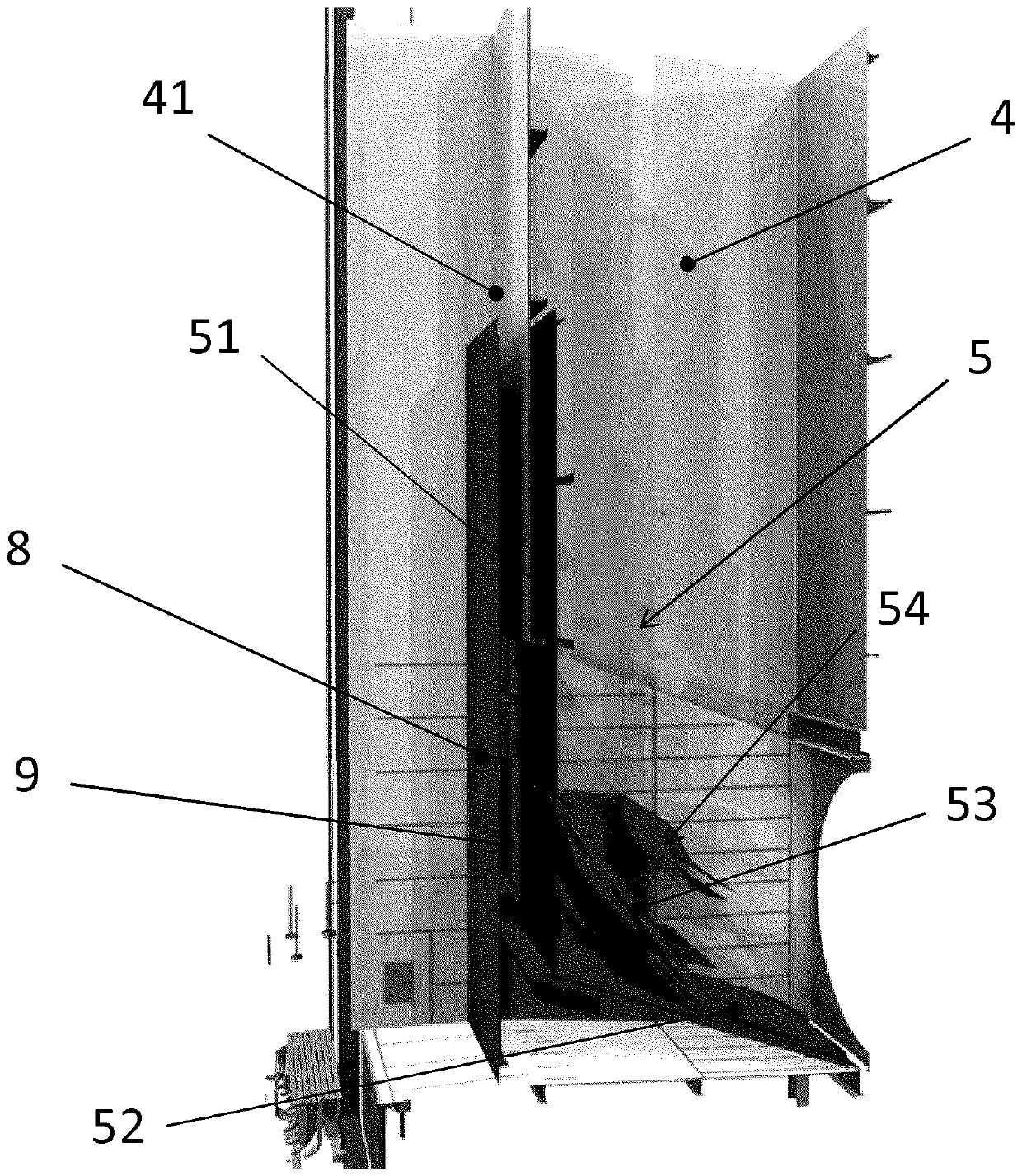
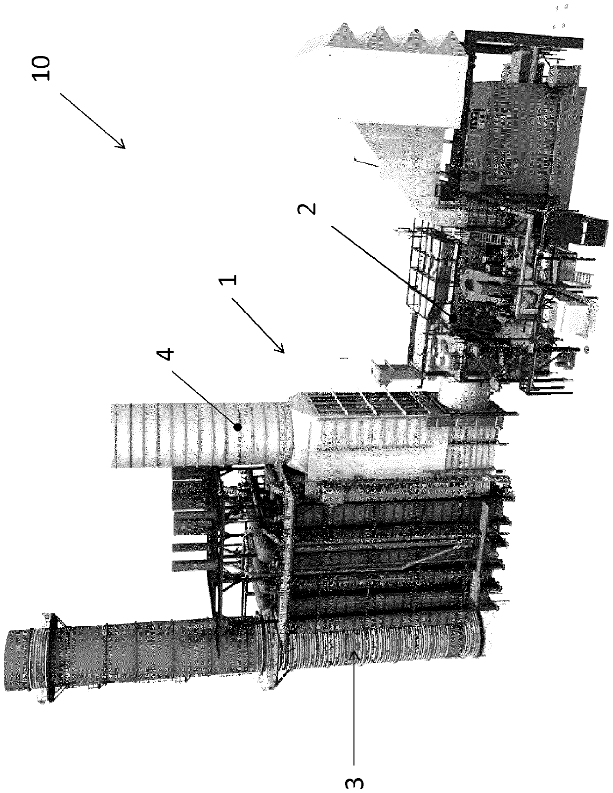
[0025] see figure 1 , generally shows a combined cycle plant 10 . The combined cycle plant includes a gas turbine plant 2 and a heat recovery steam generator 3 (hereinafter referred to as HRSG) associated with the steam power plant, which uses hot exhaust gas from the gas turbine to heat water and generate steam . The combined cycle plant comprises a bypass system 1 integrated within the inlet duct structure of the HRSG below the bypass chimney part indicated with reference number 4 .

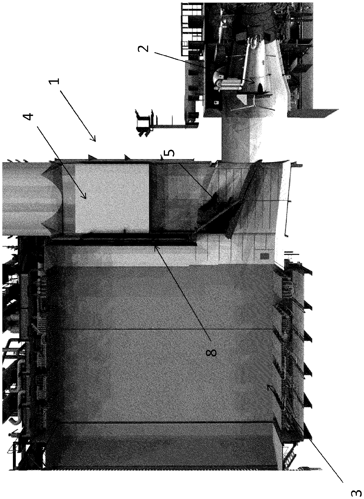
[0026] More specifically, see the next figure 2 , the hot exhaust gas flowing out of the gas turbine plant 2 from the exhaust duct 21 is allowed to enter the split system 1 . The split system 1 then refines the gas and directs it to the upper bypass stack 4 if single cycle and / or maintenance operations are required, or allows it to enter the HRSG 3 if combined cycle is required. For this purpose, the split system 1 is movable internally between a single cycle closed position where hot exha...


PUM


Abstract

The present invention generally relates to a diverting system to be used in a combined-cycle power plant. According to the invention, the diverting system is integrated within the by-pass stack and carries out, in a sole component, the functions of by-passing the hot exhaust flow in a single-cycle configuration or guiding it through the HRSG, acting as a diffusor, in an open combined-cycle configuration.

Description

technical field [0001] The present invention generally relates to a flow splitting system for use in a combined cycle power plant. Background technique [0002] As is well known, gas turbine engines generate useful work by driving a turbine shaft by means of hot gases obtained from burning compressed natural gas, such as air. To improve the overall efficiency of work production, steam power plants are arranged in combination with gas turbine plants. In this assembly, heated gases exiting the turbine flow through the exhaust duct to a heat recovery steam generator (HRSG). The heat from the gas is then used in the HRSG to heat water and generate steam, which in turn is used to drive a steam turbine. [0003] Conventional combined cycle plants as described above are equipped with splitter dampers which allow power plants including gas turbine plants and steam power plants to operate in simple cycle or combined cycle mode. For this purpose, the bypass damper is typically conf...

Claims


Application Information

Patent Timeline
Patent Type & Authority Patents(China)
IPC IPC(8): F01K11/02
CPCF01K11/02F01K23/101Y02E20/16F01D25/30F02C3/04F02C6/18F02C9/18F05D2220/32F05D2220/72
Inventor S.特里波德A.科恩伊格P.莫尔勒J.普菲斯特纳
Owner ANSALDO ENERGIA SWITZERLAND AG
Learn More