Blow-by ventilation device for internal combustion engine

A ventilation device and internal combustion engine technology, applied to mechanical equipment, engine components, machines/engines, etc., can solve problems such as inability to obtain functions, difficulty in smooth operation of one-way valves, and restrictions on component layout

Active Publication Date: 2018-07-03
SUZUKI MOTOR CORP
View PDF5 Cites 0 Cited by
  • Summary
  • Abstract
  • Description
  • Claims
  • Application Information

AI Technical Summary

Problems solved by technology

Therefore, there is a problem of constraints on the component layout of the internal combustion engine
In addition, in a cold environment, due to the freezing of the dew condensation water contained in the fresh air, it is difficult for the check valve to operate smoothly, and the original function may not be obtained.

Method used


Image

  • Blow-by ventilation device for internal combustion engine
  • Blow-by ventilation device for internal combustion engine
  • Blow-by ventilation device for internal combustion engine

Examples


Embodiment Construction

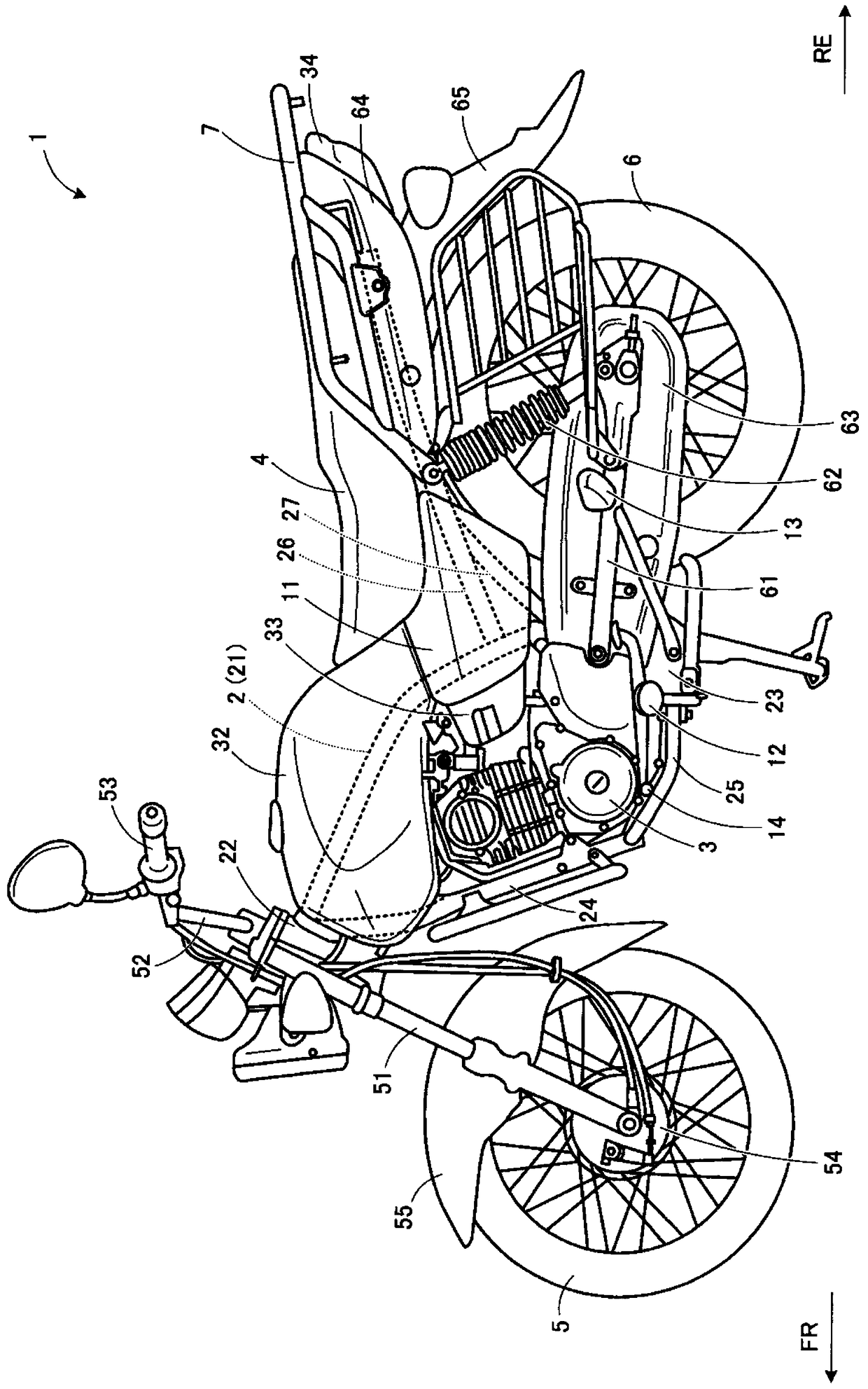
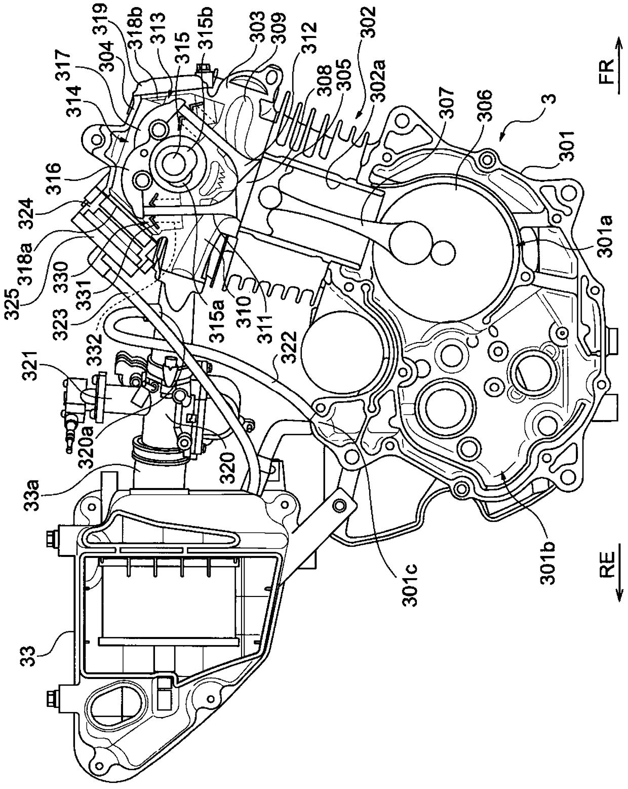
[0050] Hereinafter, this embodiment will be described in detail with reference to the drawings. In addition, an example in which the blow-by ventilator for an internal combustion engine of the present invention is applied to a street-type motorcycle will be described below, but the application object is not limited thereto and can be changed. For example, the blow-by ventilator for an internal combustion engine of the present invention can also be applied to other types of motorcycles. In addition, it can also be applied to vehicles other than motorcycles equipped with internal combustion engines (for example, auto tricycles).

[0051] figure 1 It is a side view of a motorcycle to which the blow-by ventilator for an internal combustion engine according to this embodiment is applied. In addition, in the following figures, for convenience of description, the front of the motorcycle body is represented by an arrow FR, the rear of the motorcycle by an arrow RE, the left side of ...


PUM


Abstract

The invention provides a gas carry-over exchanging device for an internal combustion engine. The layout degree of freedom of parts of the internal combustion engine can be guaranteed, and gas carry-over generated in the internal combustion engine can be exchanged properly. The gas carry-over exchanging device for the internal combustion engine is provided with a new gas supplying tubing (323), a gas carry-over discharging tubing (322) and a PCV valve unit (324). The new gas supplying tubing (323) provides clean air from an air cleaner (33) through an opening part (318a) formed in a cylinder head cover (304). The gas carry-over discharging tubing (322) discharges gas carry-over from a crankcase (301). The PCV valve unit (324) is provided with a one-way valve and is connected with the new gas supplying tubing, the one-way valve only allows air to flow from the air cleaner to the cylinder head cover, and one part of the PCV valve unit blocks the above opening part.

Description

technical field [0001] The invention relates to a blow-by air exchange device for an internal combustion engine. Background technique [0002] Conventionally, a blow-by gas ventilation device has been proposed (for example, refer to Patent Document 1), which connects a blow-by gas outlet pipe for guiding blow-by gas accompanied by clean air fed into the body of an internal combustion engine to an air cleaner, and On the one hand, the downstream end of the fresh air introduction pipe that guides clean air from the air cleaner is connected to the engine main body, and clean air is sent into the crank chamber from the cylinder head side of the internal combustion engine. [0003] In this blow-by gas exchange device, clean air from the air cleaner is sent into the crank chamber in a state heated by the cylinder head. As a result, condensation of moisture and gasoline components contained in the blow-by gas in the crank chamber can be prevented, and deterioration of oil due to m...

Claims


Application Information

Patent Timeline
Patent Type & Authority Patents(China)
IPC IPC(8): F01M13/00
CPCF01M13/00F01M2013/0038
Inventor 赤木正秋山高树太田秀邦村松武宪河野雄一
Owner SUZUKI MOTOR CORP
Why Eureka
Try Eureka