Mechanical puller for disassembling impellers and balance plates

A balance plate and impeller technology, which is applied to mechanical equipment, parts of pumping devices for elastic fluids, machines/engines, etc., can solve the problem of lack of effective disassembly tools for dismounting balance plates, balance discs and impellers, and achieve safety The coefficient is improved, it is not easy to slip, and the effect of stable pulling force

Inactive Publication Date: 2016-04-20
CHINA COAL ENERGY HEILONGJIANG COAL CHEM
View PDF8 Cites 3 Cited by
  • Summary
  • Abstract
  • Description
  • Claims
  • Application Information

AI Technical Summary

Problems solved by technology

[0003] The purpose of the present invention is to solve the problem of the current lack of effective removal tools for disassembling the balance plate, balance disc and impeller, and then provide a mechanical puller for disassembling the impeller and balance plate

Method used


Image

  • Mechanical puller for disassembling impellers and balance plates
  • Mechanical puller for disassembling impellers and balance plates
  • Mechanical puller for disassembling impellers and balance plates

Examples


specific Embodiment approach 1

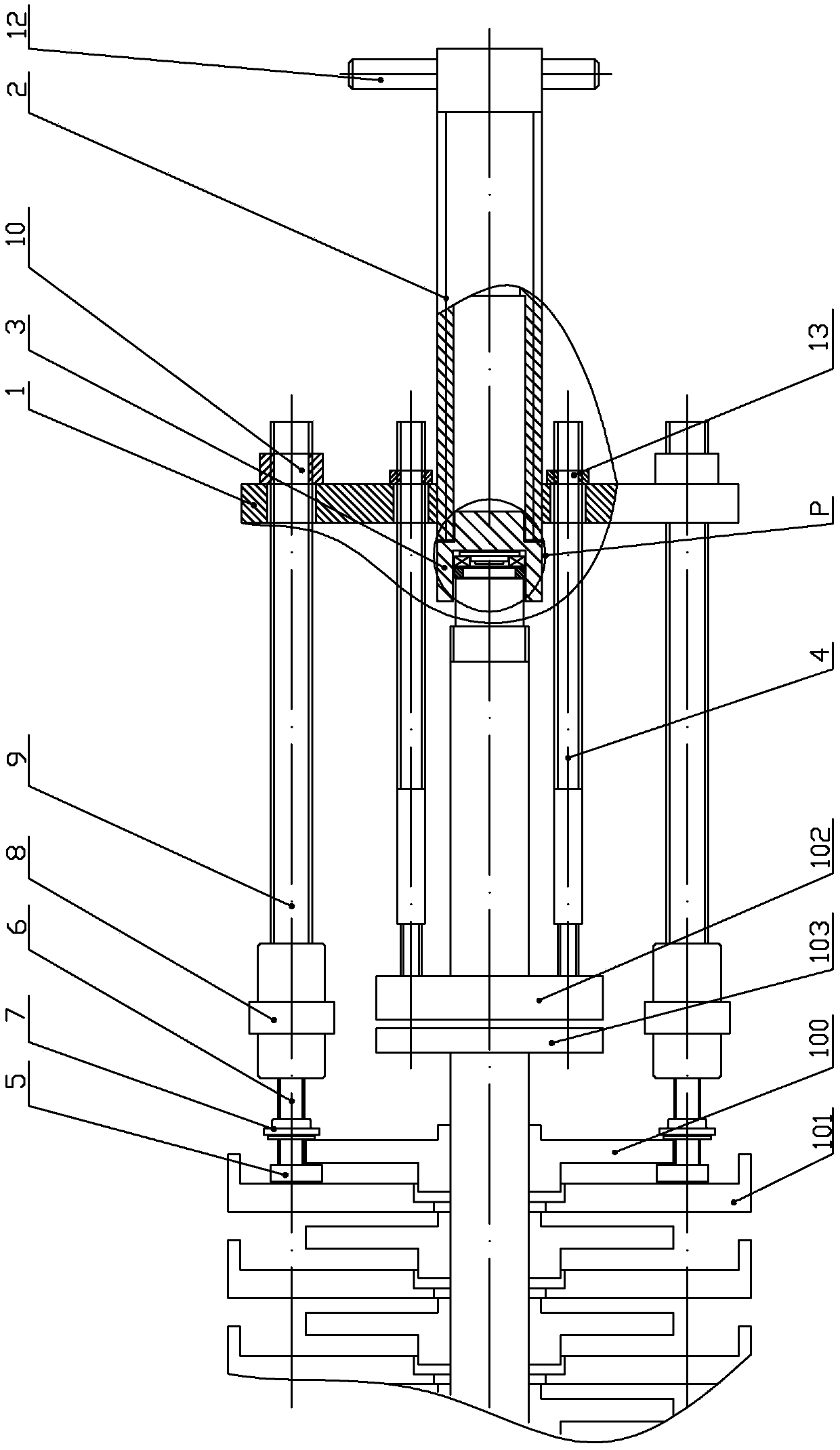
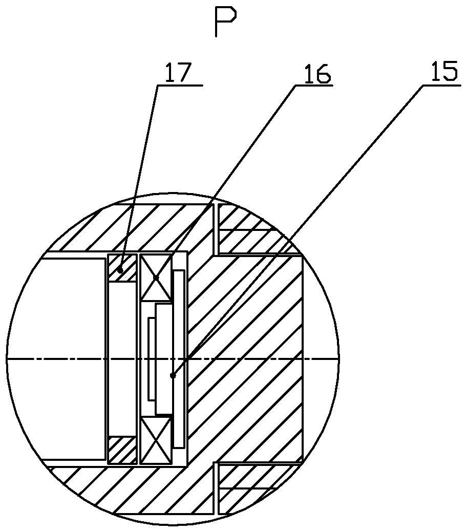
[0030] Specific implementation mode one: combine Figure 1 to Figure 14 , Figure 17 and Figure 18 Describe this embodiment, the mechanical puller used for removing the impeller and the balance plate in this embodiment includes a connection plate 1, a top screw 2, a top sleeve 3, two sets of impeller removal devices and two second screw screws 4,

[0031] Each set of impeller removal device includes pull plate 5, connecting bolt 6, first lock nut 7, connection nut 8, first lead screw 9 and second lock nut 10, and two sets of impeller removal devices are arranged symmetrically about the central axis of the impeller , the tie plate 5 is located between the first-stage impeller 100 and the first-stage pump section 101, the connecting bolt 6 is located at the outer circle of the first-stage impeller 100, one end of the connecting bolt 6 is screwed to the tie plate 5, and the tie plate 5 is connected to the first-stage impeller One end surface of 100 is in close contact with the...

specific Embodiment approach 2

[0038] Specific implementation mode two: combination figure 1 , Figure 8 and Figure 9 In describing this embodiment, the thickness of the pull plate 5 is less than 7 mm. This design ensures that the pull plate can be smoothly placed between the impeller and the pump section. Other compositions and connections are the same as those in the first embodiment.

specific Embodiment approach 3

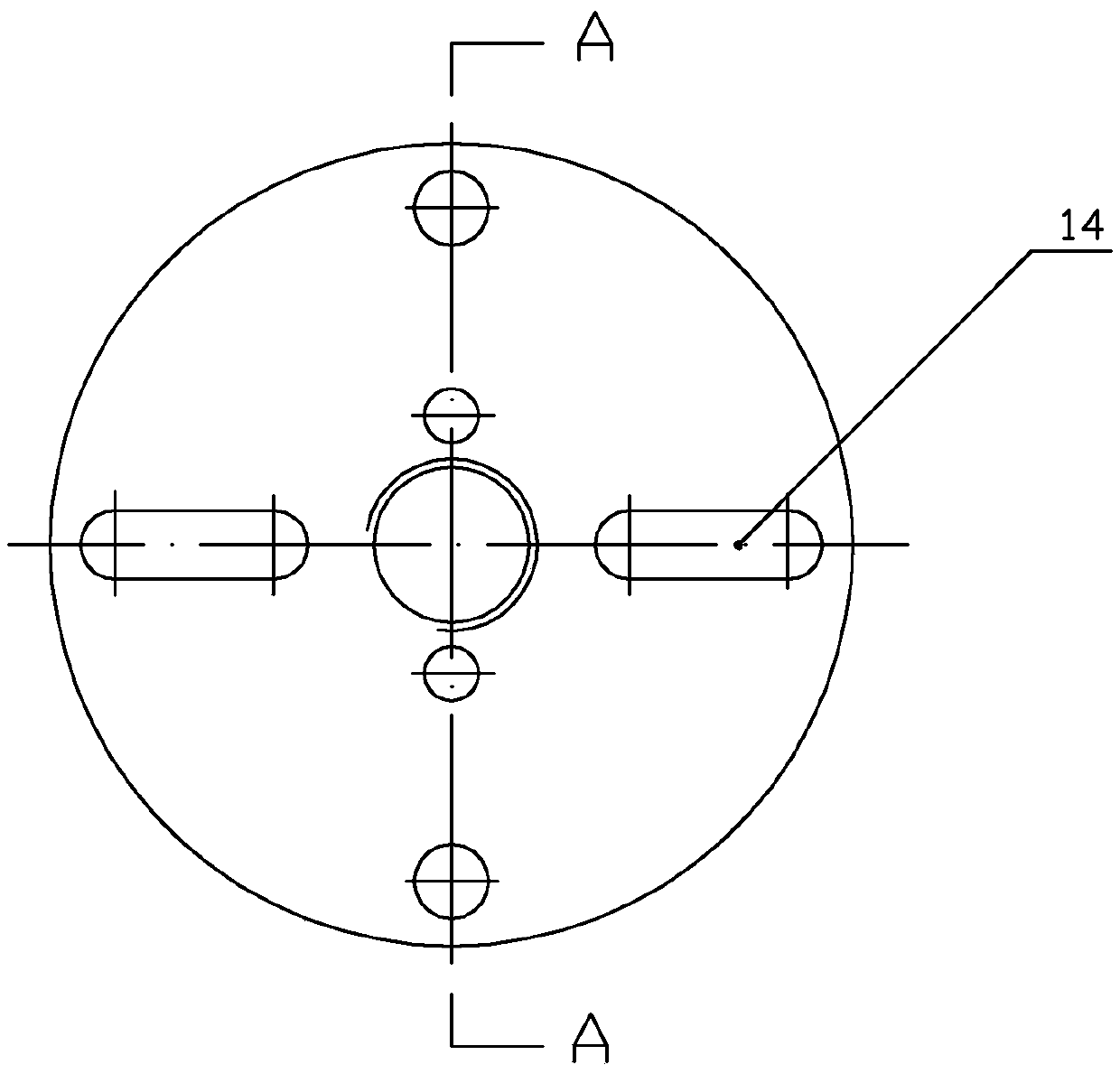
[0039] Specific implementation mode three: combination image 3 To illustrate this embodiment, the connecting plate 1 is also processed with two long holes 14 arranged symmetrically along its central axis. With this design, for parts that need to be disassembled on other shafts (such as bearings, bushings and gears of various specifications), the top sleeve that matches the diameter of the corresponding shaft end can be replaced, and the screw can be inserted into the long hole on the connecting plate. Arbitrary placement can be used to disassemble other parts on the shaft, which makes the disassembly puller more versatile and safer, and greatly improves the value of parts and disassembly efficiency. Other compositions and connections are the same as those in Embodiment 1 or Embodiment 2.


PUM


Abstract

The invention relates to a mechanical puller for disassembling impellers and balance plates. The problem of lacking of a tool capable of effectively disassembling the balance plates, balance disks and the impellers at present is solved. Two impeller disassembling devices are arranged in a symmetrical mode according to a central axis of the impellers, each pulling plate is located between the corresponding first-stage impeller and first-stage pump section, one end of each connecting bolt is connected with the corresponding pulling plate in a threaded mode, each pulling plate makes close contact with one end face of the corresponding first-stage impeller through a first lock nut arranged on the corresponding connecting bolt, the other end of each first lead screw is installed on a corresponding connecting plate in a penetrating mode and locked through a second lock nut, one end of each head jackscrew is matched with one end of a corresponding ejector bush machined with a shoulder, each head jackscrew is installed in the center of the corresponding connecting disk in a penetrating mode and connected with the connecting disk in a threaded mode, and each balance plate is fixedly connected with the corresponding connecting plate through a second lead screw and a third lock nut. The mechanical puller is used for disassembling the impellers and the balance plates.

Description

technical field [0001] The invention relates to a mechanical puller, in particular to a mechanical puller for removing an impeller and a balance plate. Background technique [0002] During the maintenance process of multi-stage pumps, it is difficult to disassemble the shaft, impeller and balance disc due to the serious adhesion between the balance plate, balance disc and impeller and the shaft, and there is no effective disassembly tool. The strength of prying the impeller with a crowbar is not enough, and the hook head of the hydraulic puller cannot be used to grab the impeller (puller: suitable for railway vehicle maintenance, mechanical installation, mine maintenance, support of construction projects, and general heavy lifting and lowering. It can still disassemble the pulleys, gears, bearings and other round workpieces in various mechanical equipment.), because the gap between the impeller and the pump section is only 7mm, the thickness of the hydraulic puller head exce...

Claims


Application Information

Patent Timeline
Patent Type & Authority Applications(China)
IPC IPC(8): F04D29/60
CPCF04D29/60
Inventor 潘志力姜海潮王永安
Owner CHINA COAL ENERGY HEILONGJIANG COAL CHEM
Why Eureka
Try Eureka