Self-centering sealing piece for achieving floating through gas pressure difference action and mounting method of self-centering sealing piece

A seal and pressure difference technology, applied in the field of self-concentric seals, can solve problems such as unfavorable sealing performance, applicable line speed and temperature restrictions, and achieve the effect of improving safety and economy

Active Publication Date: 2016-04-20
SHENYANG AEROSPACE UNIVERSITY
View PDF5 Cites 8 Cited by
  • Summary
  • Abstract
  • Description
  • Claims
  • Application Information

AI Technical Summary

Problems solved by technology

However, when sealing gas, the floating seal should be filled with lubricating oil (such as the sealing shoe used to seal hydrogen at the end of the generator shaft) to facilitate sealing and lubrication, so an additional oil circuit system is required
[0004] The main application limitation of the traditional floating seal is that it is generally not suitable for the sealing of high-temperature gas; in some special occasions, although the selection of special materials (such as graphite) allows direct contact with the rotor without auxiliary sealing oil, there are also relatively strict Strict applicable line speed and temperature limitations
Due to the low viscosity of the gas, extremely high rotational speed or line speed is required to form a dynamic pressure gas film. Therefore, even if it is applied to the sealing of high-temperature gas, the floating seal and the surface of the rotor are generally in a state of dry friction, which is not conducive to its long-term stable sealing performance.

Method used


Image

  • Self-centering sealing piece for achieving floating through gas pressure difference action and mounting method of self-centering sealing piece
  • Self-centering sealing piece for achieving floating through gas pressure difference action and mounting method of self-centering sealing piece
  • Self-centering sealing piece for achieving floating through gas pressure difference action and mounting method of self-centering sealing piece

Examples


Embodiment 1

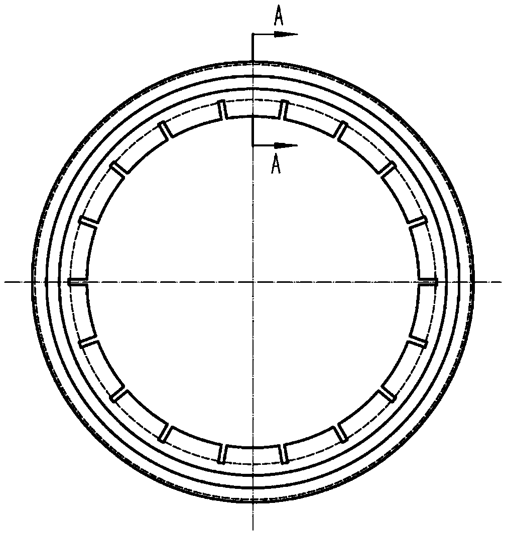
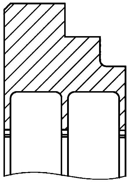
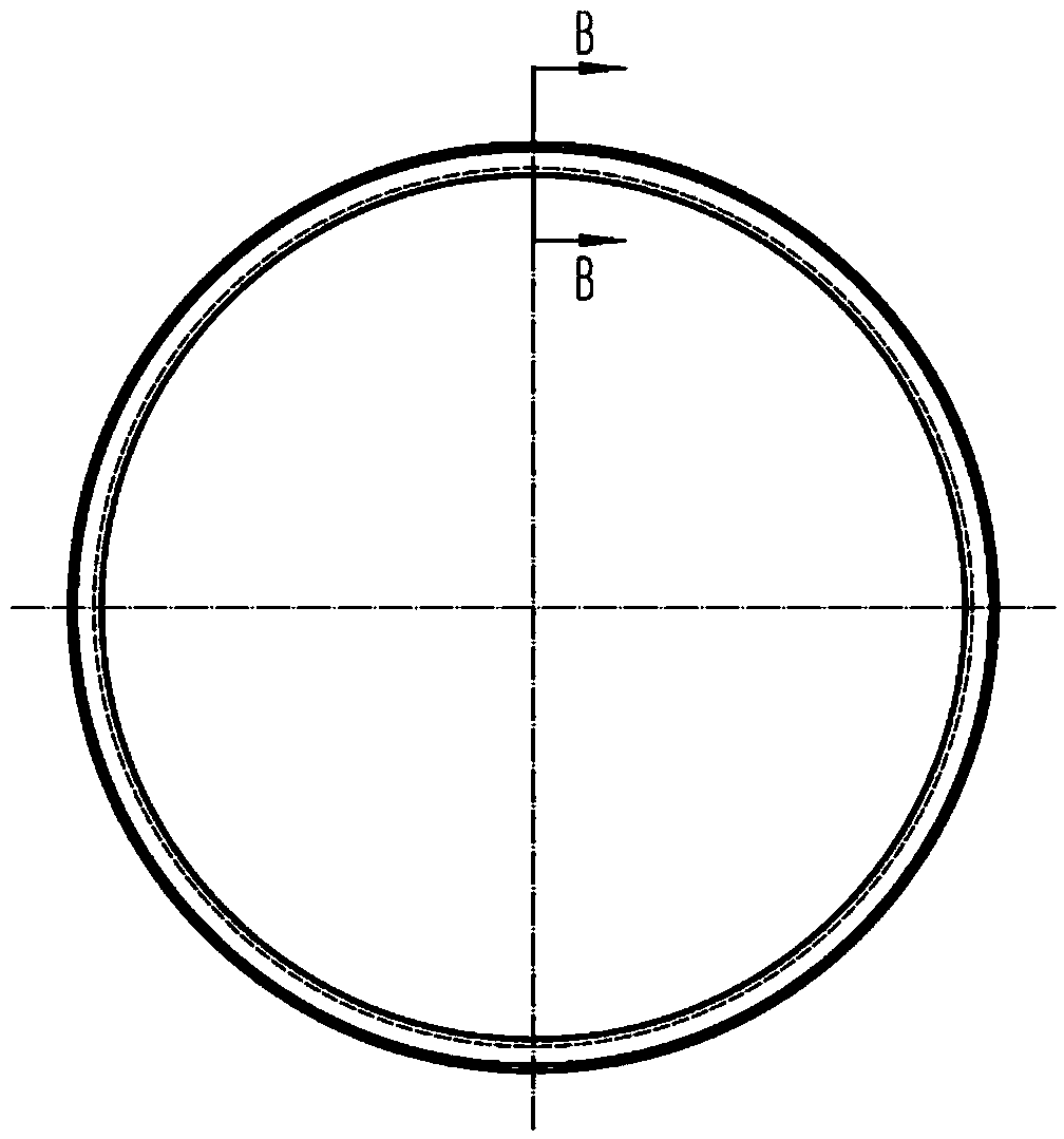
[0034] like Figure 1-7 As shown, a self-concentric seal that utilizes the effect of gas pressure difference to realize floating is applied to the shaft end of a certain type of aero-engine. Composed of the ball retaining ring 4, the main seal ring 1 is a three-tooth labyrinth structure, and the three seal teeth are concentric, and the inner diameters of the first seal tooth 31 and the second seal tooth 32 on the high-pressure side are both φ120.6mm, and the last on the low-pressure side The inner diameter of a sealing tooth 33 is φ120.4mm, and the outer diameter of the rotor 13 matched therewith is φ120mm. 18 circumferential spacers 2 are inlaid and welded on the main sealing ring 1. The circumferential spacers 2 are rectangular and have a thickness of 1.95 mm. φ120.3mm. The ball retaining ring 4 is closely matched with the main sealing ring 1, and forms a circular track on the low-pressure side 22 to accommodate the anti-friction ball 3. The diameter of the anti-friction b...

Embodiment 2

[0040] The seal of this embodiment is applied to the shaft end of the main helium fan of a nuclear power unit. Since the main helium fan adopts a magnetic suspension bearing, there is often a large amount of transient rotor jump, and the traditional labyrinth seal is difficult to adapt to long-term continuous operation. . The seal applied to the shaft end of the main helium blower and the installation method are similar to those in Embodiment 1, and the only difference is the specific size, which will not be repeated here.


PUM


Abstract

A self-centering sealing piece for achieving floating through gas pressure difference action comprises a main sealing ring, circumferential spacers, a friction reducing ball and a ball retaining ring. The main sealing ring is of a labyrinth seal structure and is provided with at least two sealing teeth, sealing clearances formed between the sealing teeth and a rotor are not completely equal, and the low-pressure side sealing clearances are not larger than the high-pressure side sealing clearances. A labyrinth sealing cavity is divided into a plurality of tooth cavities through the circumferential spacers, so that the labyrinth sealing cavity is of a bag type structure. The ball retaining ring is matched with the main sealing ring. The main sealing ring is circumferentially provided with a plurality of radial slots, and the circumferential spacers are inserted into the radial slots in the radial direction. In the mounting process, it is guaranteed that the clearance between the attaching faces of a sealing cover and a sealing seat is as small as possible, and an auxiliary sealing ring is arranged between the matching faces of the sealing cover and a sealing piece body. The inner side of the auxiliary sealing ring is communicated with the high-pressure side, and the outer side of the auxiliary sealing ring is communicated with the low-pressure side. A rotating preventing pin is arranged between the sealing piece body and the sealing seat or the sealing cover. According to the self-centering sealing piece for achieving floating through gas pressure difference action, the advantages of traditional labyrinth sealing and floating sealing are integrated, and the defects of traditional labyrinth sealing and floating sealing are abandoned.

Description

technical field [0001] The invention relates to a self-concentric sealing member which realizes floating by the effect of gas pressure difference and an installation method thereof, belonging to the field of rotary mechanical seals. Background technique [0002] Labyrinth seals are not limited by rotation speed, temperature and pressure difference, so they are widely used in turbo equipment such as compressors, steam turbines, gas turbines, and aeroengines. However, the labyrinth seal also has its own defects that are difficult to overcome. Generally, it is necessary to reserve a large enough gap to avoid possible friction due to rotor eccentricity and over-critical speed; even so, the labyrinth seal is often damaged due to transient friction. resulting in a permanent widening of the gap. [0003] The traditional floating seal mainly relies on the buoyancy of the liquid film formed by the high-speed rotation of the rotor to maintain a non-contact state with the rotor, and c...

Claims


Application Information

Patent Timeline
Patent Type & Authority Applications(China)
IPC IPC(8): F16J15/447
CPCF16J15/447
Inventor 孙丹韦红旗石伟伟艾延廷周海仑田晶
Owner SHENYANG AEROSPACE UNIVERSITY
Why Eureka
Try Eureka