Novel wood floor drying plant

A technology for drying equipment and wood floors, applied in the field of wood floor manufacturing, can solve the problems of single function and poor drying effect, etc.

Active Publication Date: 2016-04-20
蚌埠格识知识产权运营有限公司
View PDF5 Cites 8 Cited by
  • Summary
  • Abstract
  • Description
  • Claims
  • Application Information

AI Technical Summary

Problems solved by technology

[0004] But this invention has the problems of poor drying effect and single function

Method used


Image

  • Novel wood floor drying plant
  • Novel wood floor drying plant
  • Novel wood floor drying plant

Examples


Embodiment

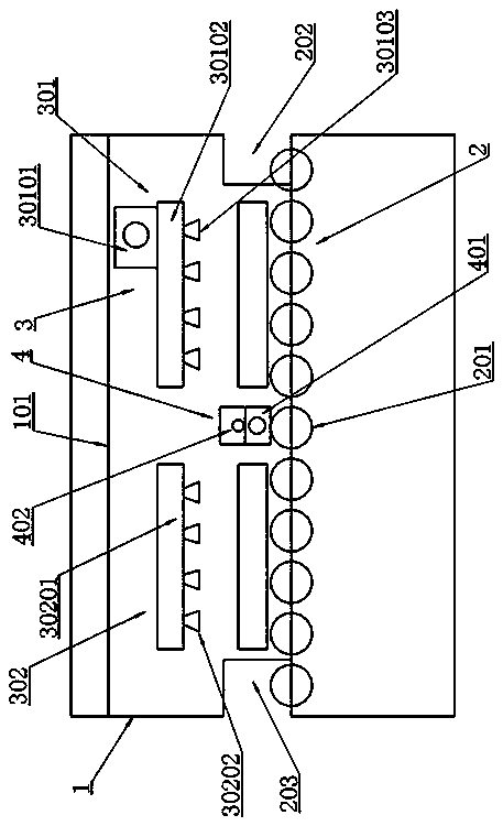
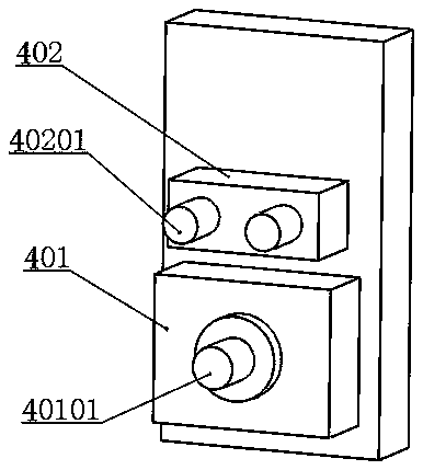
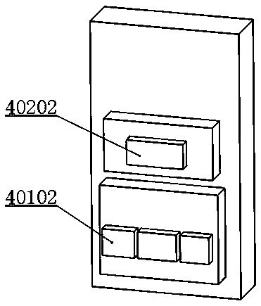
[0021] Example: as attached figure 1 , attached figure 2 and attached image 3 As shown, a new type of wood floor drying equipment includes a frame 1, a conveying unit 2 arranged in the frame 1 and a drying unit 3 above the conveying unit 2, and a drying unit 3 arranged in the conveying unit 2 and the photoelectric detection unit 4 between the drying unit 3, the photoelectric detection unit 4 includes a counting photoelectric part 401 and a flat detection photoelectric part 402, and the drying unit 3 includes a hot air quick drying unit 301 and a normal drying Dry unit 302 . This setting makes the drying equipment integrate the functions of drying, counting and flatness detection, and has the advantages of good drying effect, accurate counting of the floor, and high detection accuracy of floor surface lift.

[0022] The photoelectric detection unit 4 includes a photoelectric transmitting frame and a photoelectric receiving frame, and the photoelectric transmitting frame an...


PUM


Abstract

The invention belongs to the technical field of wood floor manufacturing, and particularly relates to a novel wood floor drying plant which comprises a machine frame, a delivering unit arranged in the machine frame, a drying unit arranged above the delivering unit, and a photoelectric detection unit arranged between the delivering unit and the drying unit, wherein the photoelectric detection unit comprises a counting photoelectric part and a flat detection photoelectric part; and the drying unit comprises a hot air quick drying unit and a common drying unit. The novel wood floor drying plant is used for carrying out drying operation on the floor, has the functions of drying, counting and flatness detection, and has the advantages of favorable drying effect and high counting and detection precision.

Description

technical field [0001] The invention belongs to the technical field of wood floor manufacturing, and in particular relates to a novel wood floor drying equipment. Background technique [0002] In the production process of wood flooring, drying treatment is required after the painting process is completed. Present wooden floor drying device generally is to arrange heating tube above wooden floor, utilizes heating tube heating to dry the paint on wooden floor upper surface, utilizes the natural temperature in drying box to dry the back paint of wooden floor bottom surface again. However, the back paint on the bottom surface of the wooden floor that has been dried in this way is not completely dry. When stacking and transporting the wooden floors, the wooden floors are stacked together. The back paint on the bottom surface of the upper wooden floor is easy to pollute the back paint on the upper surface of the lower wooden floor, resulting defective product. [0003] The Chine...

Claims


Application Information

Patent Timeline
Patent Type & Authority Applications(China)
IPC IPC(8): F26B15/12F26B21/00F26B25/22G06M1/272G01B21/30
CPCF26B15/122F26B21/003F26B25/22F26B2210/14G01B21/30G06M1/272
Inventor 钱世峰
Owner 蚌埠格识知识产权运营有限公司
Why Eureka
Try Eureka