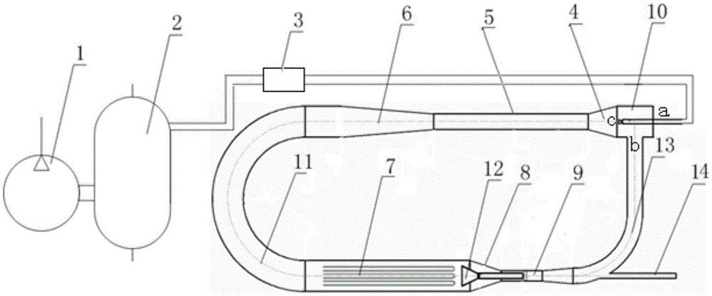
Backflow type high temperature hot wind tunnel structure

A warm and wind tunnel technology, used in thermometers, measuring heat, thermometer testing/calibration, etc., can solve the problems of large dispersion of calibration data, high calibration cost, and high energy consumption, and achieves reduction of dispersion and energy. Consumption and calibration cost, the effect of improving uniformity

Active Publication Date: 2016-04-20
AECC SICHUAN GAS TURBINE RES INST
5 Cites 4 Cited by

AI-Extracted Technical Summary

Problems solved by technology

The special-shaped temperature sensor usually cannot be calibrated because its temperature-sensing rod section cannot be placed in the constant temperature zone of the furnace
Domestically developed a hot wind tunnel using a direct current wind tunnel for dynamic c...

Method used

The present invention forms the air supply system of backflow hot wind tunnel with air compressor and air storage tank, and air compressor is stored in the air storage tank after air is compressed to certain pressure, as the gas source of hot wind tunnel operation. The air storage tank that comes with the air compressor has a small volume. If the air is directly supplied by the air compressor during the operation of the hot wind tunnel, the pressure fluctuation will be large, which will lead to unstable flow rate in the hot wind tunnel, resulting in large fluctuations in the power of the electric heater, which is not conducive to Realization of stable temperature field in hot wind tunnel. After adding the air storage tank, the pressure in the air storage tank is stable during the operation of the hot wind tunnel, so the flow rate of the hot wind tunnel is also stable.
[0012] The electric heater plays the role of heating air flow. Due to the backflow effect of the backflow wind tunnel, before the airflow temperature is stable, the temperature of the airflow entering the electric heater is different each time, and the temperature rises gradually, which also achieves the goal of keeping the airflow a...

Abstract

The invention belongs to the calibration field of a temperature sensor, and relates to a backflow type high temperature hot wind tunnel structure for calibrating the temperature sensor. The backflow type high temperature hot wind tunnel structure includes an air compressor (1), an air storage tank (2), a control valve (3), a first convergence section (4), a mixing section (5), a diffusion section (6), a heating section (7), a second convergence section (8), and a test section (9). The backflow type high temperature hot wind tunnel structure is characterized by comprising a jet injection section (10), a semicircle section (11), and a backflow section (13). The backflow type high temperature hot wind tunnel structure for calibrating the temperature sensor greatly improves the uniformity of a temperature field, decreases the dispersibility of calibration data, reduces the energy consumption and the calibration cost, and is suitable for static state metering detection.

Application Domain

Thermometer testing/calibration

Technology Topic

Transducer calibrationJet flow +7

Image

  • Backflow type high temperature hot wind tunnel structure

Examples

  • Experimental program(1)

Example Embodiment

[0007] The present invention will be described in further detail below. see figure 1 , a backflow type high-temperature hot air tunnel structure, including an air compressor 1, an air storage tank 2, a control valve 3, a first converging section 4, a mixing section 5, a diffusing section 6, a heating section 7, a second converging section 8 and Test section 9: the air outlet of the air compressor 1 is connected with the air inlet of the air storage tank 2, the air outlet of the air storage tank 2 is connected with the inlet of the control valve 3 through a pipeline, and the air outlet of the first convergent section 4 is connected with the mixing section 5 is communicated with the air inlet, the air outlet of the mixing section 5 is communicated with the air inlet of the diffusion section 6, the air outlet of the heating section 7 is communicated with the air inlet of the second convergent section 8, and the air outlet of the second convergent section 8 is connected with The air inlet of the test section 9 is connected; it is characterized in that: there is a jet injection section 10, a semi-circular arc section 11 and a return section 13; the outlet of the control valve 3 passes through the pipeline and the injector inlet 10a of the jet injection section 10 Connected, the air outlet 10c of the jet ejection section 10 is communicated with the air inlet of the first convergent section 4, the air inlet of the semicircle section 11 is communicated with the air outlet of the diffusion section 6, and the air outlet of the semicircle section 11 is connected with The air inlet of the heating section 7 is communicated, the air inlet of the backflow section 13 is communicated with the air outlet of the test section 9, the air outlet of the backflow section 13 is communicated with the suction port 10b of the jet injection section 10, and on the backflow section 13 there is a An exhaust pipe 14 communicating with the atmosphere.
[0008] In order to further improve the uniformity of the temperature field, there is a temperature equalizer 12, which is composed of the converging bell mouth section of the front section and the circular pipe section at the rear end. There is a swirler at the front end of the circular pipe section, and the temperature equalizer 12 is located at the second converging In section 8 and test section 9, the converging bell mouth section of the temperature equalizer 12 is located at the air inlet of the second converging section 8, and the round pipe section of the temperature equalizer 12 is located in the test section 9 and in front of the test model.
[0009] The working principle of the present invention is: the present invention applies the backflow hot air tunnel structure to realize the recycling of the heat energy of the heated air flow. The circulating air flow is gradually heated up by the electric heater, and the constant temperature field required for the calibration of the temperature sensor for the test is formed by adding isolation sections, cyclones and other measures to optimize the temperature field in the shrinkage section and the test section of the hot air tunnel. The gradual heating of the cycle reduces the power of the heater, thereby reducing the volume and floor space of the hot wind tunnel, because compared with the one-time heating method of the direct-flow hot wind tunnel, the heating distance of the heater in the return flow hot wind tunnel (also That is, the heater length) is much smaller, which not only reduces the construction cost of the heater, but also reduces the overall length of the hot wind tunnel. The reduction in the power of the electric heater also greatly reduces the operating cost of the hot wind tunnel.
[0010] The present invention uses an air compressor and an air storage tank to form an air supply system for a recirculation hot wind tunnel. The air compressor compresses the air to a certain pressure and stores it in the air storage tank as an air source for the operation of the hot wind tunnel. The air storage tank of the air compressor has a small volume. If the air is directly supplied by the air compressor during the operation of the hot wind tunnel, the pressure fluctuation will be large, which will lead to unstable flow rate in the hot wind tunnel, resulting in large fluctuations in the power of the electric heater, which is not conducive to Realization of stable temperature field in hot wind tunnel. After adding the air storage tank, the pressure in the air storage tank is stable during the operation of the hot wind tunnel, so the flow rate of the hot wind tunnel is also stable.
[0011] The present invention uses the ejector as the driving force for the operation of the hot wind tunnel. The conventional low-speed normal temperature wind tunnel usually uses a motor to drive the fan to pressurize as the power system of the wind tunnel. And it is expensive, difficult to cool the linkage shaft, difficult to seal and lubricate between the linkage shaft and the hole, and other technical problems. In this design, the ejector pressurization method is used as the operating power of the hot wind tunnel, which avoids the above technical problems. The nozzle pipe in the injector structure feeds the air compressed by the air compressor. During operation, the temperature of the airflow flowing in the nozzle pipe is much lower than that of the airflow outside the pipe, and the flow rate is much greater than the flow rate of the airflow passing through the pipe. In this way, the airflow in the tube plays a role in cooling the nozzle during operation, avoiding the deformation of the nozzle during the operation of the hot wind tunnel, so as to ensure the stability of the position of the nozzle, thereby maintaining the stable operation of the hot wind tunnel.
[0012] The electric heater acts to heat the air flow. Due to the backflow effect of the backflow wind tunnel, before the airflow temperature is stable, the temperature of the airflow entering the electric heater is different each time, and the temperature rises gradually, which also achieves the goal of keeping the airflow at a certain temperature point and lowering the temperature when running stably. The power of the electric heater and the purpose of reducing the length of the electric heater not only save the construction cost, but also greatly reduce the operating cost. In the present invention, the structure of the electric heater is evenly distributed, the heating pipe is parallel to the direction of the airflow, and the airflow sweeps the heating pipe outward. In this way, the electric heater not only plays the role of heating the airflow, but also achieves the effect of combing the flow field, that is, directing the airflow.
[0013] The isolation section is used to collect the high-temperature gas flowing out from the middle of the heater to reduce the temperature gradient of the flowing gas in the isolation section, and the cyclone is used to enhance the mixing intensity of the flowing air flow in the isolation section to make the temperature more uniform.
[0014] In one embodiment of the present invention, the air compressor 1 , the air storage tank 2 , the control valve 3 , the heating section 7 and the temperature equalizer 12 are all finished products. Tests have proved that the uniformity of the temperature field in this embodiment is improved by more than 30%.

PUM

no PUM

Description & Claims & Application Information

We can also present the details of the Description, Claims and Application information to help users get a comprehensive understanding of the technical details of the patent, such as background art, summary of invention, brief description of drawings, description of embodiments, and other original content. On the other hand, users can also determine the specific scope of protection of the technology through the list of claims; as well as understand the changes in the life cycle of the technology with the presentation of the patent timeline. Login to view more.

Similar technology patents

Light guide plate and backlight assembly using the same

ActiveUS20080231590A1improve uniformity
Owner:SAMSUNG DISPLAY CO LTD

Preparation method of ultrafine tungsten carbide powder

ActiveCN103408015AImprove uniformityavoid uneven mixing
Owner:ZHUZHOU HARD ALLOY GRP CO LTD

Multiple-channel transmit magnetic resonance

InactiveCN101283286AImprove uniformityReduce SAR
Owner:KONINKLIJKE PHILIPS ELECTRONICS NV

Classification and recommendation of technical efficacy words

  • Improve uniformity
  • Small dispersion

High performance lithium ionic cell cathode material and method for producing the same

InactiveCN101162775AImprove uniformityImprove overall electrical performance
Owner:CHINA ELECTRONIC TECH GRP CORP NO 18 RES INST

Prediction method for high-cycle fatigue life of single crystal air film hole member

PendingCN108334716Aavoid nonlinearitySmall dispersion
Owner:NORTHWESTERN POLYTECHNICAL UNIV

Electric power system short circuit fault test device capable of precisely controlling short circuit time

ActiveCN104569725Afast actionSmall dispersion
Owner:FOSHAN POWER SUPPLY BUREAU GUANGDONG POWER GRID +1

Lens module assembling process

InactiveCN103984076ASmall dispersionshorten the time
Owner:LITE ON ELECTRONICS (GUANGZHOU) LTD

Perpendicular Magnetic Recording Medium and Perpendicular Magnetic Recording/Reproducing Apparatus

InactiveUS20070259214A1small dispersionhigh capability
Owner:TAKAHASHI MIGAKU +2
Why Eureka
Try Eureka