
Winding pin mechanism of winding machine and winding machine

A winding machine and rolling needle technology, which is applied in battery assembly machines, sustainable manufacturing/processing, climate sustainability, etc., can solve the problems of complex tension control, large angular velocity changes, and affecting the quality of equipment winding batteries. Achieve the effects of convenient winding control, reduced tension fluctuation, and simple structure

Inactive Publication Date: 2016-04-20
WUXI LEAD INTELLIGENT EQUIP CO LTD
View PDF6 Cites 13 Cited by
  • Summary
  • Abstract
  • Description
  • Claims
  • Application Information

AI Technical Summary

Problems solved by technology

[0002] In the prior art, the needle winding mechanism in the automatic winding equipment often adopts a two-half structure. The radial section of the winding core composed of the two halves of the needle winding is generally flat, and the winding of the power lithium battery cell often adopts a constant line. Speed ​​winding method, due to the wide width of the power lithium battery cell, when the flat core is used to wind the base material, the angular velocity changes greatly, which leads to complex tension control and ultimately affects the quality of the equipment winding cell

Method used


Image

  • Winding pin mechanism of winding machine and winding machine
  • Winding pin mechanism of winding machine and winding machine

Examples


Embodiment Construction

[0015] The present invention will be further described below in conjunction with specific drawings and embodiments.

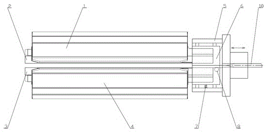
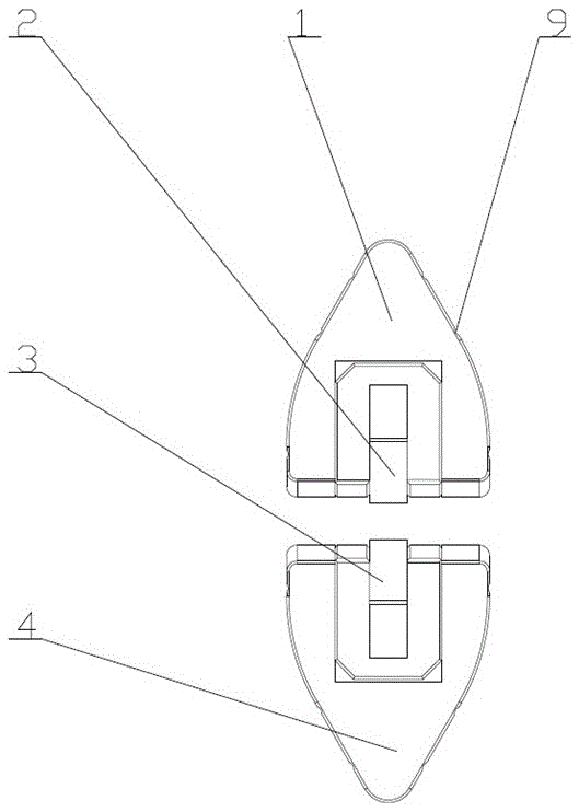
[0016] like Figure 1-Figure 2 As shown, the needle winding mechanism according to the embodiment of the present invention includes a needle winding seat, a needle winding assembly, and a needle winding tail stock, and the needle winding assembly is respectively inserted into the needle winding seat and the needle winding tail stock, and the needle winding seat is omitted in this drawing.

[0017] The needle rolling assembly includes a first outer rolling needle 1, a first inner pressing needle 2, a second inner pressing needle 3, and a second outer rolling needle 4, and the first outer rolling needle 1 and the second outer rolling needle 4 are on the same circumference Placed at 180°, the first outer rolling needle 1 is provided with the first inner pressing needle 2, the second outer rolling needle 4 is provided with the second inner pressing needle 3, the ta...


PUM


Abstract

The invention discloses a winding pin mechanism for a winding machine and the winding machine. The winding pin mechanism comprises a winding pin seat, a winding pin assembly and a winding pin tailstock. The winding pin assembly is inserted into the winding pin seat and the winding pin tailstock and comprises a first outwards-winding pin, a first inwards-pressing pin, a second inwards-pressing pin and a second outwards-winding pin, wherein the first outwards-winding pin and the second outwards-winding pin are arranged on the same circumference at 180 degrees, the first inwards-pressing pin is arranged in the first outwards-winding pin, and the second inwards-pressing pin is arranged in the second outwards-winding pin. The winding pin tailstock comprises a fixing seat, a driving device for controlling a sliding block to slide is arranged in the fixing seat and can drive the first inwards-pressing pin and the second outwards-winding pin to get close to or be away from the first outwards-winding pin and the second inwards-pressing pin to clamp or release a base material penetrating through the part between the first inwards-pressing pin and the second inwards-pressing pin. The cross section of a winding core formed by the first outwards-winding pin and the second outwards-winding pin is oval or diamond. The winding pin mechanism for the winding machine and the winding machine are simple in structure and capable of reliably winding high-quality battery cores.

Description

technical field [0001] The invention relates to the field of battery cell manufacturing, in particular to a needle winding mechanism and a winding machine. Background technique [0002] In the prior art, the needle winding mechanism in the automatic winding equipment often adopts a two-half structure. The radial section of the winding core composed of the two halves of the needle winding is generally flat, and the winding of the power lithium battery cell often adopts a constant line. The speed winding method, due to the wide width of the power lithium battery cell, uses a flat core when winding the base material, and the angular velocity changes greatly, which leads to complex tension control and ultimately affects the quality of the equipment winding cell. Contents of the invention [0003] The present invention aims to solve one of the technical problems in the related art at least to a certain extent. Therefore, the present invention proposes a needle winding mechanis...

Claims


Application Information

Patent Timeline
Patent Type & Authority Applications(China)
IPC IPC(8): H01M10/04
CPCH01M10/0409Y02P70/50
Inventor 王燕清丁华
Owner WUXI LEAD INTELLIGENT EQUIP CO LTD
Learn More