Visible camera communication system employing LED lamp MIMO array configuration

A technology of LED lamps and communication systems, which is applied in the field of visible light camera communication systems using the MIMO array architecture of LED lamps. It can solve the problems of low transmission information rate and complex processing of multi-frame fringe images by the receiver, so as to improve the information transmission rate, Speed ​​up the decoding processing time and meet the real-time effect

Active Publication Date: 2016-04-20
SYSU CMU SHUNDE INT JOINT RES INST +1
View PDF7 Cites 35 Cited by
  • Summary
  • Abstract
  • Description
  • Claims
  • Application Information

AI Technical Summary

Problems solved by technology

However, the information transmission rate of this visible light camera communication system driven by FSOOK modulation is very low, and the receiver’s processing of multi-frame stripe pictures is also relatively complicated, and it is nece

Method used


Image

  • Visible camera communication system employing LED lamp MIMO array configuration
  • Visible camera communication system employing LED lamp MIMO array configuration
  • Visible camera communication system employing LED lamp MIMO array configuration

Examples


Embodiment Construction

[0021] The drawings are for illustrative purposes only, and should not be construed as limitations on this patent; in order to better illustrate this embodiment, some parts in the drawings will be omitted, enlarged or reduced, and do not represent the size of the actual product;

[0022] For those skilled in the art, it is understandable that some well-known structures and descriptions thereof may be omitted in the drawings. The technical solutions of the present invention will be further described below in conjunction with the accompanying drawings and embodiments.

[0023] A visible light camera communication system using a MIMO-based LED lamp array architecture, including:

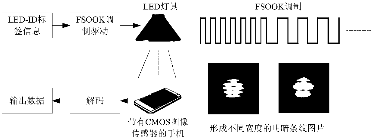
[0024] The system transmitter adopts a MIMO array structure containing multiple LED wicks, each of which is equipped with an independent FSOOK modulation driven power supply connected to the LED wick, and the transmitter is equipped with an LED-ID data modulation mapper and multiple FSOOK modulation Th...


PUM


Abstract

The invention discloses a visible camera communication system employing LED lamp MIMO array configuration. A transmitter employs the MIMO array configuration, and each LED lamp wick is provided with an independent FSOOK modulation drive power supply. The transmitter is provided with an LED-ID data modulation mapper connected with the FSOOK modulation drive power supplies. The interior of the LED-ID data modulation mapper is provided with an information mapping table in a preset manner, and the LED-ID data modulation mapper enables serial binary LED-ID data to be modulated into a plurality of parallel FSOOK frequency signals according to an information mapping rule, enables the signals to be mapped to the plurality of independent FSOOK modulation drive power supplies, and drives all lamp wicks to flicker at different frequencies. A receiver employs a CMOS image sensor with a roller shutter mechanism for photographing an LED array light source, and the exposure time needs to be selected during photographing, so as to prevent excessive exposure from causing high light noise interference. A light source forms a plurality of stripe images with different dark and bright stripe widths on the CMOS sensor, and the receiver obtains the complete image composed of a plurality of stripe subimages, and then carries out the decoding of the image.

Description

technical field [0001] The present invention faces the field of LED visible light communication positioning, and proposes a visible light camera communication system adopting an LED lamp multiple-input multiple-output (MIMO) array architecture. Background technique [0002] Using a mobile phone with a CMOS image sensor (CIS) to receive the LED light signal can realize low-rate information transmission by detecting the light and dark stripe pictures formed by the flashing LED. In order to make the blinking LEDs form a light and dark fringe picture on the imaging plane, the CMOS image sensor should use a rolling shutter. Some technologies have proposed a visible light communication system such as figure 1 As shown, the transmitter uses an LED light source driven by on-off keying (OOK) modulation, and the receiver uses a CMOS image sensor to form a light and dark fringe picture, and the OOK signal is demodulated by image processing the light and dark fringe picture. Prior Art...

Claims


Application Information

Patent Timeline
IPC IPC(8): H04B10/116H04B7/04H04N5/235
CPCH04B7/0452H04B7/0456H04B10/116H04N23/745
Inventor 李正鹏江明
Owner SYSU CMU SHUNDE INT JOINT RES INST
Why Eureka
Try Eureka