Frequency converter

A frequency converter and radiator technology, applied in the field of frequency converters, can solve the problems of hindering air flow, occupying the air duct space of the radiator, and increasing the cost, so as to achieve the effects of reducing cost, solving heat dissipation, and reducing volume

Active Publication Date: 2016-04-20
SHENZHEN INVT ELECTRIC
View PDF8 Cites 4 Cited by
  • Summary
  • Abstract
  • Description
  • Claims
  • Application Information

AI Technical Summary

Problems solved by technology

However, this method of arranging electrolytic capacitors in the radiator air duct to achieve heat dissipation takes up a lot of space in the radiator air duct, hinders the air flow, and cannot meet the temperature rise requirements inside the inverter
In order to meet the temperature rise requirements, the internal space of the inverter is currently increased to promote heat dissipation, but this method increases the volume of the inverter, increases the cost, and has certain restrictions on the use of the inverter space, which is not conducive to the inverter Promoted application of

Method used


Image

  • Frequency converter
  • Frequency converter

Examples


Embodiment Construction

[0017] In order to enable those of ordinary skill in the art to more clearly understand the purpose, technical solutions and advantages of the invention, the invention will be further described below with reference to the accompanying drawings and embodiments.

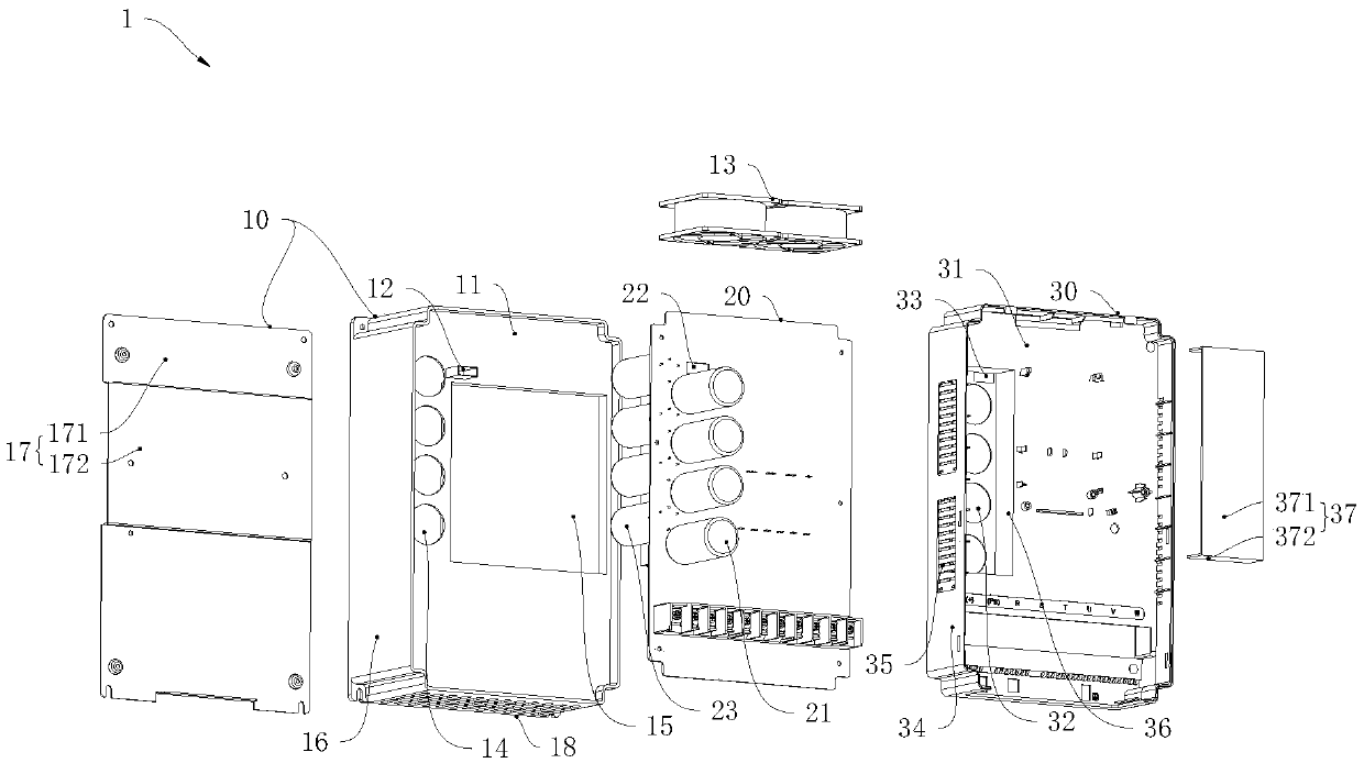
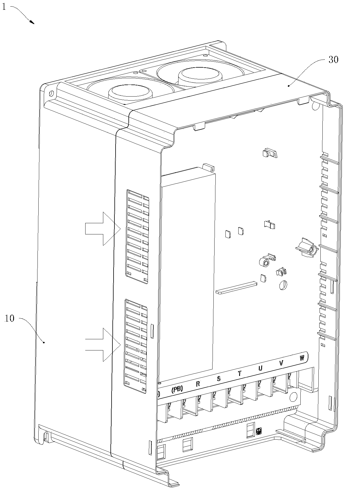
[0018] Reference Figure 1 to Figure 2 Shown are an exploded view and an assembly view of a frequency converter in a preferred embodiment. In this embodiment, the frequency converter 1 includes a first box body 10, a second box body 30 covering the first box body 10, and a first top plate 11 and a second box body 30 arranged on the first box body 10. In the driving board 20 between the second bottom plates 31, a number of first electrolytic capacitors 21 are provided on the side of the driving board 20 close to the second box 30, and a second ventilation hole 22 is provided near the first electrolytic capacitor 21, The second bottom plate 31 is provided with a first through hole 32 through which the first electrolytic ca...


PUM


Abstract

The invention provides a frequency converter comprising a first box body, a second box body covering the first box body, and a driving plate arranged between a first top plate arranged at the first box body and a second base plate arranged at the second box body. A plurality of first electrolytic capacitors are arranged at one side, approaching the second box body, of the driving plate; and a second ventilation hole is formed at the place adjacent to the first electrolytic capacitors. First through holes where the first electrolytic capacitors pass and a first ventilation hole corresponding to the second ventilation hole are formed in the second base plate. A first air flue port and an air outlet communicated with the first air flue port are formed in the first box body; and the first air flue port protrudes from the first top plate and penetrates the second ventilation hole and the first ventilation hole. External air flows through the first electrolytic capacitors and then flows out of the air outlet through the first air flue port. According to the invention, an independent heat radiation air flue is provided for the first electrolytic capacitors arranged on the driving plate, so that a problem of heat radiation of the first electrolytic capacitors can be solved. Moreover, the frequency converter has advantages of small size and low cost.

Description

Technical field [0001] The invention relates to the technical field of frequency converters, in particular to a frequency converter that meets the heat dissipation requirements of electrolytic capacitors. Background technique [0002] The inverter is equipped with a fan and a driving board. The electrolytic capacitor installed on one side of the driving board is located in the air duct of the radiator. The rotation of the fan encourages external air to flow in from the air inlet at the bottom of the inverter and flow out from the air outlet through the air duct of the radiator. , In order to realize the heat dissipation of the electrolytic capacitor and the forced air cooling inside the inverter. However, this method of arranging electrolytic capacitors in the air duct of the radiator to achieve heat dissipation occupies a large amount of space in the air duct of the radiator, hinders air flow, and cannot meet the temperature rise requirements inside the inverter. In order to me...

Claims


Application Information

Patent Timeline
Patent Type & Authority Applications(China)
IPC IPC(8): H05K7/20
CPCH05K7/20145
Inventor 张诗银刘春夏
Owner SHENZHEN INVT ELECTRIC
Why Eureka
Try Eureka