Heat treatment jig

A fixture and mounting surface technology, applied in lighting and heating equipment, furnaces, capacitors, etc., can solve the problems of uniform exposure to ambient gas, difficult placement of ceramic molded objects, and quality heating deviations

Active Publication Date: 2016-04-20
MURATA MFG CO LTD
View PDF5 Cites 0 Cited by
  • Summary
  • Abstract
  • Description
  • Claims
  • Application Information

AI Technical Summary

Problems solved by technology

[0004] However, it is difficult to uniformly mount the ceramic molded body on the mounting surface of the flat heat treatment jig, and it is difficult to make the degree of contact with the ambient air uniform, so the quality after firing tends to vary due to uneven heating.

Method used


Image

  • Heat treatment jig
  • Heat treatment jig
  • Heat treatment jig

Examples


Embodiment approach 1

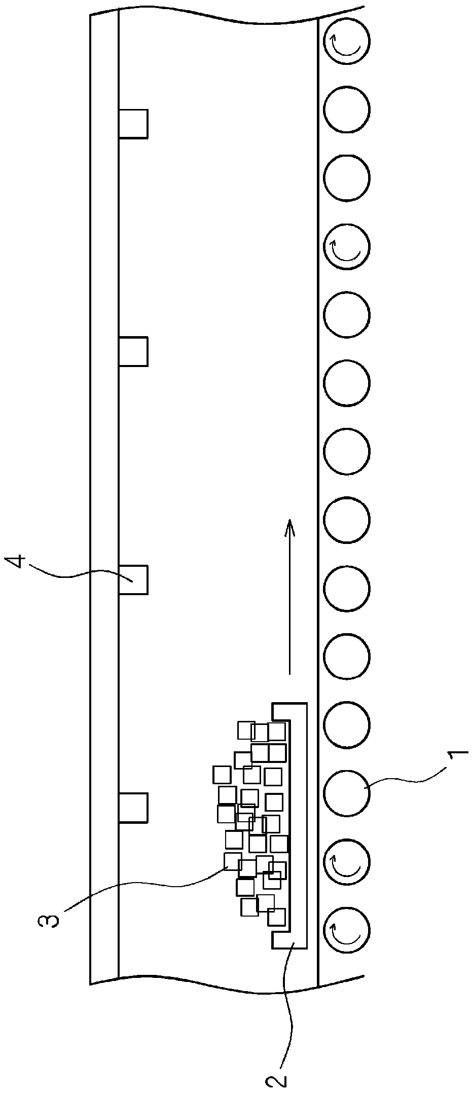
[0036] figure 1 It is a schematic diagram showing the structure of a heating device using a conventional heat treatment jig. exist figure 1 In , a so-called roller system heating device is shown. Such as figure 1 As shown, a plurality of rotatable rollers 1 are provided on the bottom surface of the furnace of the heating furnace (heat treatment furnace) of the heating device, and chip-shaped (ceramic) electronic components 3, such as chip-shaped ceramic capacitors, chip-shaped inductors, etc. The stacked bodies are randomly stacked on the mounting surface of the jig 2 for heat treatment, and they are passed in the heating furnace in the direction of the arrow in the figure. The heated ambient gas is jetted from the gas jet port 4 in the upper part of the heating furnace to heat-treat the chip-shaped electronic component 3 passing therethrough. Of course, the gas ejection port 4 is not limited to be provided in the upper part of the heating furnace, and may be provided in t...

Embodiment approach 2

[0051] The jig for heat treatment in Embodiment 2 is the same as Embodiment 1 in the following respects: it includes a mounting surface with a plurality of through holes, and the mounting surface is composed of folded concave-convex surfaces with alternately folded peaks and folded valleys. The tops of the folded peaks at or near both ends of the jig are higher than the heights of the tops of the other folded peaks. However, the mounting surface on which chip-shaped electronic components are placed has the lowest height at the top of the central folded peak, and the height of the top of the folded peak gradually increases toward both ends, which is different from that of the embodiment. One is different.

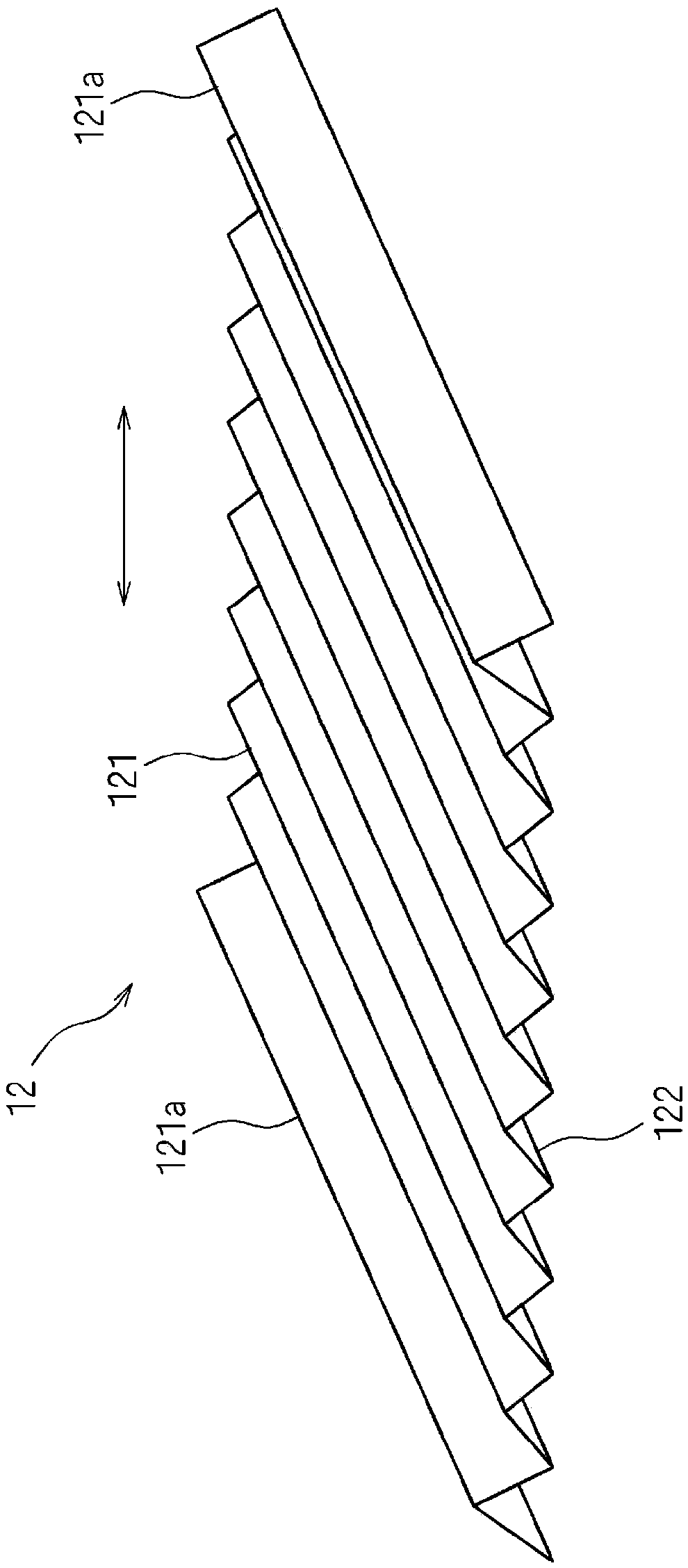
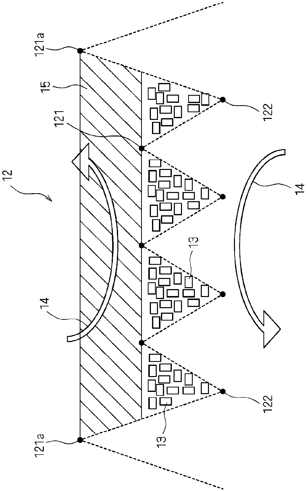
[0052] Figure 4 It is a schematic cross-sectional view when chip-shaped electronic components 13 are placed on heat treatment jig 12 according to Embodiment 2 of the present invention. Such as Figure 4 As shown, the mounting surface of the heat treatment jig 12 is made ...

Embodiment approach 3

[0059] The jig for heat treatment in Embodiment 3 is the same as Embodiment 1 and Embodiment 2 in the following aspects: it includes a mounting surface with a plurality of through holes, and the mounting surface is a wrinkled concave-convex surface that alternately repeats folded peaks and folded valleys. In this configuration, the tops of the folded peaks located at or near both ends in the folding direction are higher than the tops of the other folded peaks. However, it is different from Embodiment 1 and Embodiment 2 in that the mounting surfaces on the side closer to both ends in the folding direction are erected vertically for each group of mounting surfaces adjacent to each other via the folded peak portion.

[0060] Figure 5 It is a schematic cross-sectional view when a chip-shaped electronic component is placed on the heat treatment jig 12 according to Embodiment 3 of the present invention. Such as Figure 5 As shown in (a), the mounting surface of the heat treatment...


PUM


Abstract

Provided is a heat treatment jig that makes it possible to maintain the flow path of an ambient gas and maintain sufficient structural strength using a simple configuration. A heat treatment jig (12) according to the present invention comprises a loading surface having a plurality of through holes. The loading surface is configured from a bellows-like uneven surface in which ridge folds and valley folds repeat in an alternating manner. The heights of the peak sections (121a) of ridge fold sections at both ends or in the vicinity of both ends of the loading surface are higher than the heights of the peak sections (121) of the other ridge fold sections. The peak section (121) of a central ridge fold section has the lowest height, and it is preferable that the bellows-like uneven surface be formed so that the heights of the peak sections (121) of the ridge fold sections gradually become higher as the proximity to both ends in the repeating fold direction increases.

Description

technical field [0001] The present invention relates to a jig for heat treatment used for heat treatment of chip-shaped ceramic electronic components. Background technique [0002] In the process of manufacturing chip-shaped ceramic electronic components, heat treatments such as debinder treatment and firing treatment of ceramic molded bodies are performed using heating devices such as continuous heat treatment furnaces and batch heat treatment furnaces. For example, when firing the ceramic molded body (heat treatment), the ceramic molded body is passed through the heat treatment furnace in a state where the ceramic molded body is housed in a jig for heat treatment. [0003] The jig for heat treatment has a mounting surface on which the ceramic molded body is mounted, and is generally formed in a flat plate shape. In order to heat-treat more ceramic electronic components at once, a plurality of jigs for heat treatment may be stacked and used at predetermined intervals in th...

Claims


Application Information

Patent Timeline
Patent Type & Authority Applications(China)
IPC IPC(8): H01G13/00F27D5/00
CPCF27D5/00H01G13/00
Inventor 秋本茂平子広一郎森井博史
Owner MURATA MFG CO LTD
Why Eureka
Try Eureka