Optical binding device and method

An optical bonding and optical device technology, applied in the optical field to reduce air bubbles and increase production efficiency

Active Publication Date: 2016-04-27
NINGBO VISION DISPLAY TECH
View PDF5 Cites 9 Cited by
  • Summary
  • Abstract
  • Description
  • Claims
  • Application Information

AI Technical Summary

Problems solved by technology

[0005] The purpose of the present invention is to solve the problems existing in the optical binding process of the existing display screen, and to provide an optical binding device and method

Method used


Image

  • Optical binding device and method
  • Optical binding device and method
  • Optical binding device and method

Examples


specific Embodiment approach 1

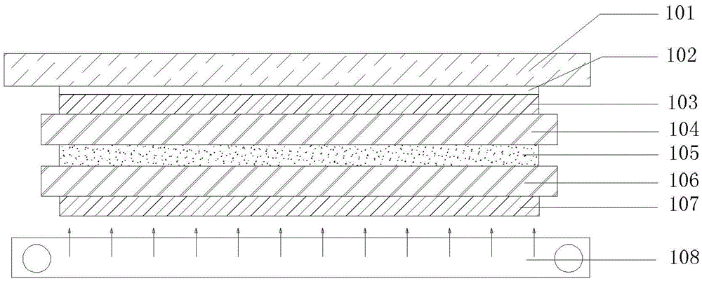
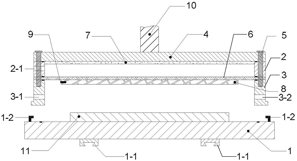
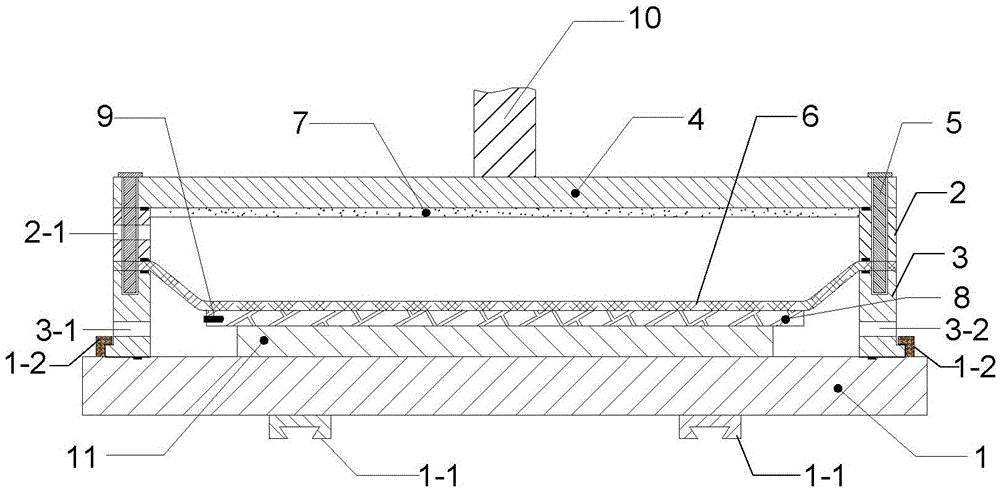
[0033] Specific implementation mode one: the following combination figure 2 and image 3 Describe this embodiment, the optical binding device described in this embodiment includes a carrying unit and a working cavity unit; the carrying unit is used to carry the optical device 11 to be bonded, and the working cavity unit is used to provide the optical device to be bonded. Pressure and thermal environment to bind the optical components to be bonded together;

[0034] The bearing unit comprises a bearing platform 1, two mutually parallel sliders 1-1 are arranged on the lower surface of the bearing platform 1, and the bearing platform 1 moves on the slide rail through the two sliders 1-1; The buckles 1-2 are parallel to each other, and the extension direction of the slider 1-1 and the buckle 1-2 is the extension direction of the slide rail;

[0035] The working chamber unit includes a pressurized chamber and a vacuum chamber; the pressurized chamber is surrounded by the side wa...

specific Embodiment approach 2

[0048] Specific Embodiment 2: This embodiment is a further description of Embodiment 1, and further includes an insulating layer 7 , and the insulating layer 7 is arranged on the lower surface of the top plate 4 .

[0049] The insulation layer 7 plays the role of heat preservation and reduces energy consumption.

specific Embodiment approach 3

[0050] Embodiment 3: The optical binding method described in this embodiment is implemented based on the optical binding device described in Embodiment 1. The method includes the following steps:

[0051] Step 1. Preparation:

[0052] a. The bearing unit and the working cavity unit are initially separated, and they are arranged separately along the extending direction of the slide rail;

[0053] b. Lift the working cavity unit so that the raised engaging part of the working cavity unit is flush with the buckle 1-2 of the carrying platform 1;

[0054] c. Control the heating layer 8 to be heated to the required working temperature;

[0055] d. placing the optical device 11 to be bonded on the carrying platform 1;

[0056] Step 2: Make the carrying unit slide along the slide rails towards the direction of the working cavity unit, make the raised engaging part of the working cavity unit slide into the buckle 1-2 of the carrying platform 1 along the horizontal direction, and snap t...


PUM


Abstract

The invention discloses an optical binding device and method, belongs to the field of optics and aims to solve the problems of a conventional optical binding technology of a display screen. According to the scheme, a bearing unit slides in a direction of a working chamber unit along slide rails, and bulge clamp parts of the working chamber unit slide into clamp buckles of a bearing platform in the horizontal direction and are completely clamped together with the clamp buckles; a vacuum chamber performs vacuum pumping, a silica gel sheet is sucked to move downwards to be tightly attached to the upper surface of a to-be-attached optical device, vacuum pumping is stopped when a vacuum degree is reached, and the attachment step is completed; an air compressor is started, a pressurizing chamber starts pressurizing work, a heating layer continuously provides a constant-temperature environment for the to-be-attached optical device, and the to-be-attached optical device is subjected to defoaming; the defoaming step is continued for 5 min; after defoaming is finished, the air compressor performs air release operation on the pressurizing chamber, the silica gel sheet drives the heating layer to move upwards, the bearing unit is controlled to move along the slide rails and is completely separated, and an optically bound part is taken out.

Description

technical field [0001] The present invention belongs to the field of optics. Background technique [0002] With the popularity of electronic products, people have higher and higher requirements for touch and display effects. Therefore, the current mobile phones, tablets, and displays with touch functions all use optical bonding technology. The screen and the like use special optical materials and processes to bond two or more structures together. The purpose of this is to reduce the air layer between the layers, thereby increasing the light transmittance of the liquid crystal display and reducing the reflection, while the structure is more stable, such as figure 1 shown. The cover glass 101 is added with a flexible circuit board and a sensor to form a touch screen ( figure 1 Only the cover glass 101 is given in the figure, and other structures are omitted), the liquid crystal display includes an upper polarizer 103, a color filter glass 104, a liquid crystal layer 105, a ...

Claims


Application Information

Patent Timeline
Patent Type & Authority Applications(China)
IPC IPC(8): B32B37/06B32B37/10B32B41/00
CPCB32B37/06B32B37/10B32B41/00
Inventor 顾开宇虞志刚邵静磊
Owner NINGBO VISION DISPLAY TECH
Why Eureka
Try Eureka