
Integrated dynamic brake apparatus

A technology of dynamic braking and equipment, applied in the direction of electric braking system, brake, brake transmission, etc., can solve problems such as increasing weight

Active Publication Date: 2016-04-27
HL MANDO CORP
View PDF6 Cites 6 Cited by
  • Summary
  • Abstract
  • Description
  • Claims
  • Application Information

AI Technical Summary

Problems solved by technology

[0009] However, since the units constituting the electronically controlled braking apparatus are separately provided and installed, it is necessary to secure the installation space due to the limitation of the installation space of the vehicle, and to increase its weight

Method used


Image

  • Integrated dynamic brake apparatus
  • Integrated dynamic brake apparatus
  • Integrated dynamic brake apparatus

Examples


Embodiment Construction

[0048] Hereinafter, an exemplary embodiment of an integrated electronically controlled dynamic brake apparatus including a worm gear and a rack and pinion according to the present invention will be described in detail with reference to the accompanying drawings. First, in adding reference numerals to elements of the drawings, the same elements are designated by the same reference numerals throughout the drawings. Also, in the description of the present invention, if it is determined that a detailed description of a known configuration or function may make the gist of the present invention unclear, the detailed description will be omitted.

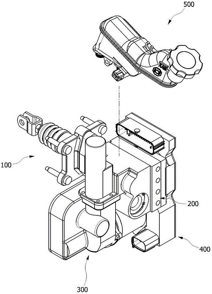
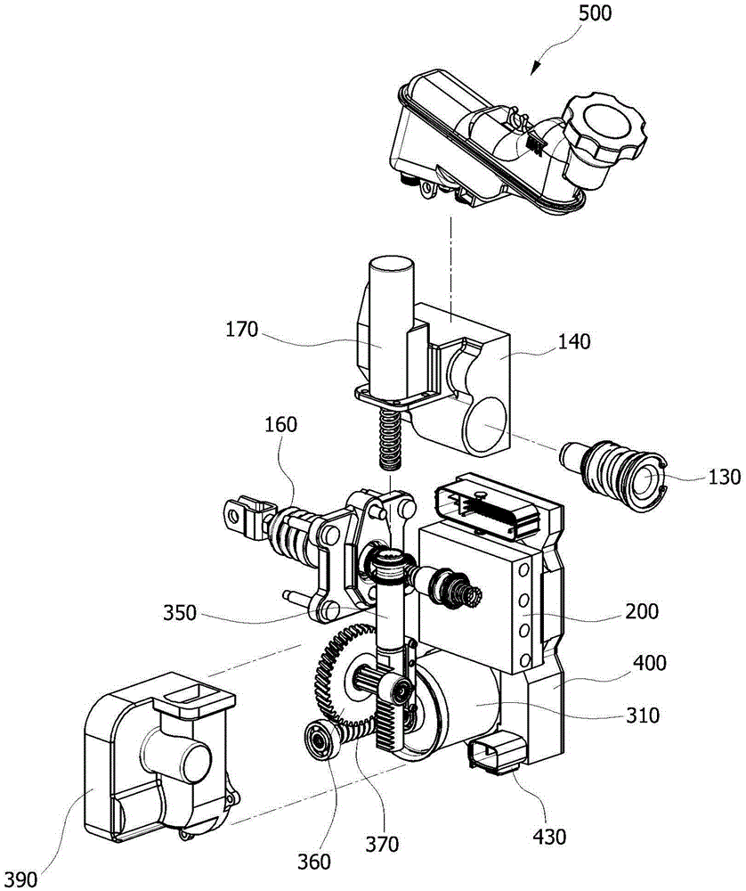
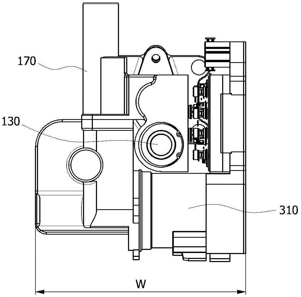
[0049] In the following, reference will be made to Figure 1-6 An integrated dynamic braking apparatus according to the present invention is described. Figure 1-4 is a perspective view, an exploded perspective view, a front view and a side view of an integrated dynamic braking device according to the present invention, Figure 5 is a view ...


PUM


Abstract

An integrated dynamic brake apparatus includes a hydraulic pressure generating unit configured to convert rotational power of a motor into linear reciprocating movement, a brake actuation unit including a master cylinder in which a pump piston included in the hydraulic pressure generating unit is accommodated, a valve block disposed over the motor and configured to control discharging of a fluid accommodated in the master cylinder, and an electronic control unit disposed at one side of the motor and configured to control the motor and the valve block, wherein the pump piston linearly reciprocates along a first axis perpendicular to an axis of rotation of the motor.

Description

technical field [0001] The present invention relates to an integrated electronically controlled dynamic braking device, and more particularly to a brake activation unit comprising a master cylinder, a pedal simulator, etc., an ABS / ESC unit and a unit configured to provide hydraulic pressure as a Integrated dynamic braking device of worm gear and rack and pinion in a single unit. Background technique [0002] In the present era, the development of hybrid vehicles, fuel cell vehicles, electric vehicles, etc. has been actively carried out to improve fuel efficiency and reduce exhaust gas. A braking device, that is, a braking device for a vehicle must be installed in such a vehicle, and here, the braking device for a vehicle is a device for reducing the speed of a moving vehicle or stopping the vehicle. Conventional braking apparatuses for vehicles are classified into vacuum brakes configured to generate braking pressure using an engine's suction pressure and hydraulic brakes c...

Claims


Application Information

Patent Timeline
Patent Type & Authority Applications(China)
IPC IPC(8): B60T13/66
CPCB60T13/66B60T8/368B60T13/745B60T7/042B60L7/26
Inventor 韩相寿
Owner HL MANDO CORP
Learn More