
An installation method for a main air-discharge pipe of a sintering machine

A technology for exhaust pipes and installation methods, which is applied in the direction of furnace types, furnaces, and charging treatment types, etc., which can solve problems such as difficult installation of pipes and large diameters, and achieve the effects of simple methods, improved utilization, and simple and fast methods

Active Publication Date: 2018-09-25
CHINA MCC20 GRP CORP +1
View PDF4 Cites 2 Cited by
  • Summary
  • Abstract
  • Description
  • Claims
  • Application Information

AI Technical Summary

Problems solved by technology

[0002] The main exhaust duct of the sintering machine is located under the ash hopper at the lower part of the sintering machine and above the bulk material belt conveyor. It is located on the second floor of the main building of the sintering machine as a whole. The diameter is large, and it runs through the plant from the head of the sintering machine to the tail of the sintering machine; therefore, it is difficult to install the pipeline

Method used


Image

  • An installation method for a main air-discharge pipe of a sintering machine
  • An installation method for a main air-discharge pipe of a sintering machine
  • An installation method for a main air-discharge pipe of a sintering machine

Examples


Embodiment Construction

[0021] A method for installing the main exhaust duct of a sintering machine, which includes the following steps:

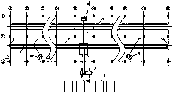
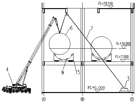
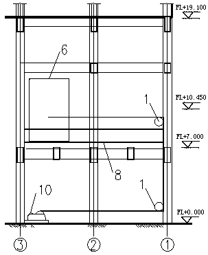
[0022] Such as Figure 1-3 As shown: the main exhaust duct is arranged in the sintering main plant building 1-19 columns, between the A-B spans and between the 1-19 columns B-C spans, here only describes the installation of the pipes between the A-B spans, and the installation steps are as follows:

[0023] The main exhaust duct is prefabricated by the factory. Since it is 128m long, it needs to be manufactured in sections. figure 1 The hoisting entrance shown is set between 9-10 columns with a spacing of 8m wide. At the same time, the butt weld of the pipe section needs to stagger the position of the pipe support;

[0024] Step 1: Check the activity of the main exhaust duct, the installation elevation and levelness of the fixed support, and perform secondary grouting after meeting the accuracy requirements. The seat and the base steel plate are welded and fixe...


PUM


Abstract

The invention relates to an installation method for a main air-discharge pipe of a sintering machine. The method includes the following steps: the first step: checking the installation elevation and levelness of a bearing of the main air-discharge pipe; the second step: fully arranging sliding rails on the bearing of the main air-discharge pipe; the third step: arranging winches in a machine head,a tail and the middle ground of a factory building; the fourth step: installing the pipe from the machine head to the middle section of the factory building; the fifth step: slipping the pipe hung onthe pipe support to the correct installation position in segment by utilizing the machine head ground position winch; the sixth step: repeating the fourth step to the fifth step and performing assembling and welding on two pipes in segment; the seventh step: lifting the spliced two sections of the pipe to a height of 200-500 mm; the eighth step: repeating the fourth step to the seventh step, andinstalling and then group welding all sections of the pipe from the machine head to the middle position of the factory building; the ninth step: installing the section of the pipe from the middle position of the factory building to the tail, and repeating the fourth step to the eighth step and splicing the whole pipe into an integral body in segment. The problem of the installation of the main air-discharge pipe in the restricted space is solved, and the rapid, concise and safety effect in the installation process is realized.

Description

technical field [0001] The invention relates to an air duct installation, in particular to a method for installing the main exhaust duct of a sintering machine. Background technique [0002] The main exhaust duct of the sintering machine is located under the ash hopper at the lower part of the sintering machine and above the bulk material belt conveyor. It is located on the second floor of the main building of the sintering machine as a whole. The diameter is large, and it runs through the plant from the head of the sintering machine to the tail of the sintering machine; therefore, the installation of the pipeline is more difficult. Contents of the invention [0003] The invention aims to overcome the defects of the prior art, provide a method for installing the main exhaust duct of a sintering machine, solve the difficult problem of installing the main exhaust duct in a confined space, and realize the effect of fast, simple and safe installation process. [0004] In orde...

Claims


Application Information

Patent Timeline
Patent Type & Authority Applications(China)
IPC IPC(8): F27B21/08
CPCF27B21/00F27M2003/04
Inventor 张阳黄克勤张长春李俊峰马永春孙兴利
Owner CHINA MCC20 GRP CORP
Learn More