Hybrid electromechanical coolant pump

A coolant pump and coolant technology, which is applied in the direction of engine cooling, mechanical equipment, engine components, etc., can solve problems such as complex operation of mechanical structures, inconsistency, etc.

Inactive Publication Date: 2016-04-27
BORG WAMER CORP
View PDF8 Cites 1 Cited by
  • Summary
  • Abstract
  • Description
  • Claims
  • Application Information

AI Technical Summary

Problems solved by technology

However, this design is mechanically complex and susceptible to operational inconsistencies

Method used


Image

  • Hybrid electromechanical coolant pump
  • Hybrid electromechanical coolant pump
  • Hybrid electromechanical coolant pump

Examples


Embodiment Construction

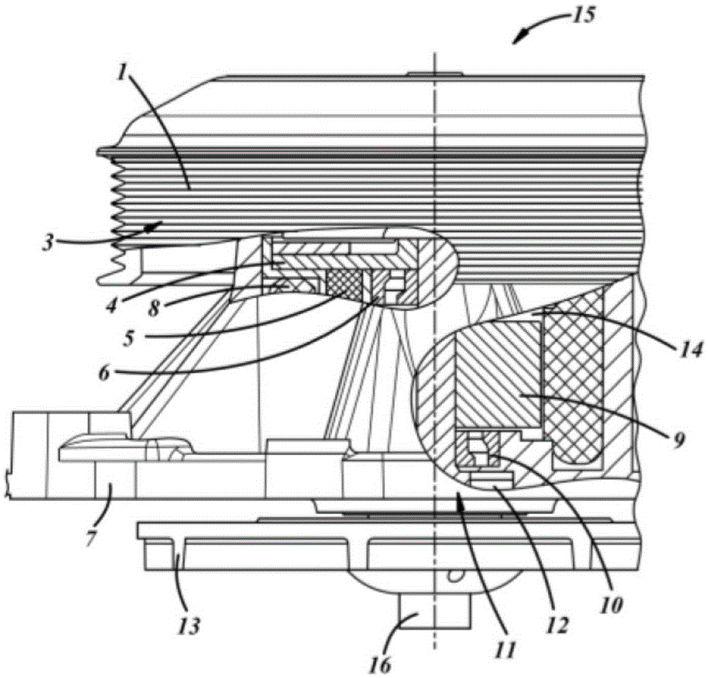
[0033] figure 1 A sectional view through the coolant pump 15 according to one embodiment of the invention is shown. The coolant pump 15 has a pump impeller (also referred to as “impeller”) arranged on a pump impeller shaft (also referred to as “impeller shaft”). The pump impeller shaft is divided into a drive part 3 and a driven part 11 . In the illustrated embodiment, the drive portion 3 is formed as a flange-shaped structure to which the mechanical drive means 1 in the form of a pulley in this example is fixedly connected in a rotatable manner. In the illustrated embodiment, the arrangement consisting of the flange-shaped structure 3 and the pulley 1 is mounted in a housing 7 via bearings 6 .

[0034] The mechanical drive 1 is connectable to an internal combustion engine of a motor vehicle, wherein in the embodiment shown a belt drive can be used. Only the pulley 1 is shown to simplify the description.

[0035] The driven part 11 of the pump wheel (impeller) shaft is mou...


PUM


Abstract

The invention relates to a coolant pump having an impeller which is arranged on a pump impeller shaft and having a drive device for the impeller, which drive device has a mechanical drive and an electric-motor drive. The impeller shaft is divided into a driving section and a driven section, and an openable and closable clutch is arranged between the driving section and the driven section. Operation of the coolant pump by either the mechanical drive or the electric-motor drive can be dependent upon a predetermined speed of threshold of rotation of the impeller, and / or upon a predetermined power usage threshold.

Description

[0001] Cross References to Related Applications [0002] This is a continuation-in-part of US Patent Application Serial No. 12 / 937,746, filed February 6, 2011, and entitled "Coolant Pump." technical field [0003] The invention relates to a coolant pump having both mechanical and electric modes of operation. Background technique [0004] A coolant pump is known from DE 10 214 637 A1. In order to be able to realize different drive operating states of a vehicle with such a coolant pump, said vehicle having an electric motor drive and an additional mechanical drive, a planetary drive drivable by the electric motor and / or the mechanical drive is provided. However, this design is mechanically complex and susceptible to operational inconsistencies. [0005] It is therefore an object of the present invention to produce a cooling pump which has a simpler and more reliable design than the prior art and whose operation is more efficient and automatically protected against failure ha...

Claims


Application Information

Patent Timeline
IPC IPC(8): F04D13/02F04D13/06F04D15/00F01P5/10F01P7/16
Inventor T·布赫兹J·罗斯
Owner BORG WAMER CORP
Why Eureka
Try Eureka