Liquid nitrogen recovering device and method
A recovery device and recovery method technology, applied to the liquid nitrogen recovery device and the recovery field, can solve the problems of high vacuum pump price, vacuum pump damage, difficult maintenance, etc., and achieve the effect of saving procurement and equipment maintenance costs, reducing energy consumption and costs.
- Summary
- Abstract
- Description
- Claims
- Application Information
AI Technical Summary
Problems solved by technology
Method used
Image

Examples
Embodiment 1
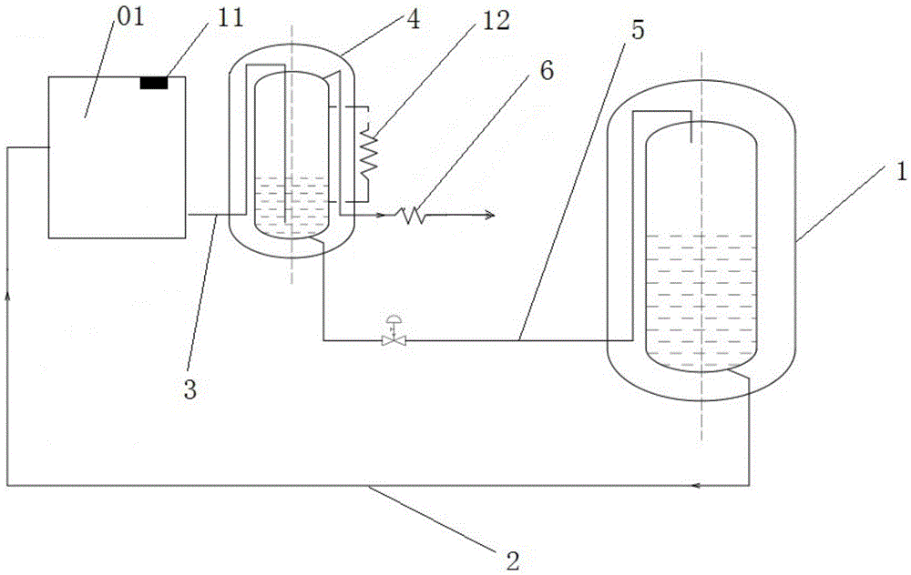
[0031] Such as figure 1 Shown, a kind of liquid nitrogen recovery device comprises:
[0032] The first liquid nitrogen storage tank 1 is used to store liquid nitrogen;
[0033] The first transportation pipeline 2 is connected to the first liquid nitrogen storage tank 1, and is used to transport the liquid nitrogen to the cryogenic working device 01;
[0034] The second transportation pipeline 3 is connected with the cryogenic working device 01;
[0035] The second liquid nitrogen storage tank 4 is connected to the second transportation pipeline 3 and is used to store the liquid nitrogen delivered by the cryogenic working device 01 through the second transportation pipeline 3;
[0036] The third transportation pipeline 5 is connected with the first liquid nitrogen storage tank 1 and the second liquid nitrogen storage tank 4 respectively, so as to transport the liquid nitrogen in the second liquid nitrogen storage tank 4 to the first liquid nitrogen storage tank 4. nitrogen t...
Embodiment 2
[0043] According to the liquid nitrogen recovery device proposed in the above embodiments, this embodiment proposes a liquid nitrogen recovery method.
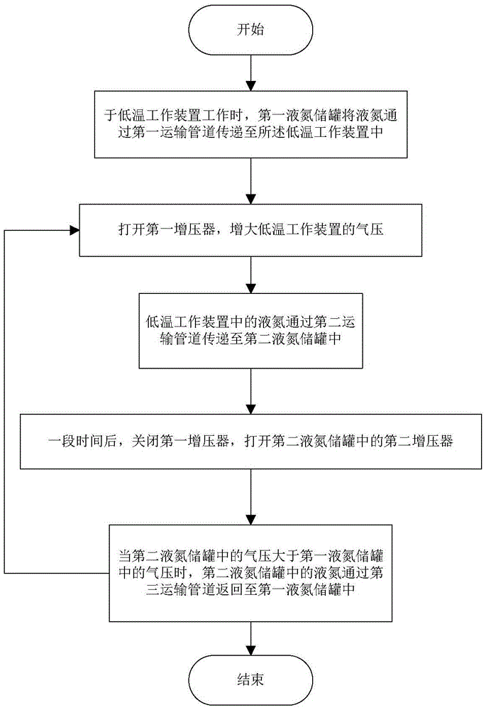
[0044] Such as image 3 Shown, a kind of liquid nitrogen recovery method comprises steps:
[0045] When the low-temperature working device 01 is working, the first liquid nitrogen storage tank 1 transfers liquid nitrogen to the low-temperature working device 01 through the first transportation pipeline 2;
[0046] Open the first supercharger 11 to increase the air pressure of the cryogenic working device 01;
[0047] The liquid nitrogen in the cryogenic working device 01 is transferred to the second liquid nitrogen storage tank 4 through the second transportation pipeline 3;
[0048] After a period of time, close the first booster 11 and open the second booster 12 in the second liquid nitrogen storage tank 4;
[0049]When the air pressure in the second liquid nitrogen storage tank 4 was greater than the air pressure in the ...
PUM
 Abstract
Description
Claims
Application Information
 - R&D
- Intellectual Property
- Life Sciences
- Materials
- Tech Scout
- Unparalleled Data Quality
- Higher Quality Content
- 60% Fewer Hallucinations
Browse by: Latest US Patents, China's latest patents, Technical Efficacy Thesaurus, Application Domain, Technology Topic, Popular Technical Reports.
© 2025 PatSnap. All rights reserved.Legal|Privacy policy|Modern Slavery Act Transparency Statement|Sitemap|About US| Contact US: help@patsnap.com