Machine vision material level gauge and its method for measuring material level

A technology of machine vision and material level gauge, which is applied in the direction of measuring devices, machines/engines, and engine lubrication, etc. It can solve the problems of ignoring parameter changes, ignoring the imaging principle characteristics of video and image equipment, complex and changeable image sizes, etc.

Active Publication Date: 2019-01-04
SHANGHAI YUNYU INTELLIGENT TECH CO LTD
View PDF13 Cites 0 Cited by
  • Summary
  • Abstract
  • Description
  • Claims
  • Application Information

AI Technical Summary

Problems solved by technology

[0029] The reason why the above existing machine vision recognition methods cannot be really used is that they ignore the imaging principle characteristics of video and image equipment: even for an image of the same area, under the same imaging focal length parameters, the farther away from the image acquisition device, the smaller the image; If you consider that zooming is required to obtain a clear image, the image size of the image of the same area is more complex and changeable in the image acquisition device
Therefore, the existing technology ignores the basic imaging principle of the image acquisition device and the more complex problems brought about by the zoom of the image acquisition device, no matter by directly acquiring the image or by comparing the image with the pre-stored image or directly calculating the projected spot area or the method of deviating from the pixel. Parameter changes cannot be truly implemented, and the accurate material level of the material cannot be obtained

Method used


Image

  • Machine vision material level gauge and its method for measuring material level
  • Machine vision material level gauge and its method for measuring material level
  • Machine vision material level gauge and its method for measuring material level

Examples


Embodiment approach 1

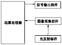
[0083] This embodiment provides a machine vision material level gauge, such as figure 1 As shown, it includes a light emitting part, an image acquisition part, an operation processor and a signal output part. Both the light emission part and the image acquisition part are set in the measurement space where the material to be tested is located, and the operation processor is respectively connected to the image acquisition part and the signal output part. ;

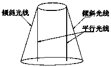
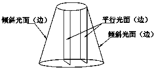
[0084] The light emitting part is used to project at least two beams of parallel light perpendicular to a certain cross-section of the material to be tested and at least one beam of oblique light at a preset angle with each parallel light to the surface of the material to be tested;

[0085] The image acquisition part is used to collect images of parallel light spots and oblique light spots formed after each parallel light and each oblique light irradiates the surface of the material to be tested, and sends the images to th...

Embodiment approach 2

[0096] This embodiment is a specific example of Embodiment 1. In this embodiment, the light emitting part and the image acquisition part are both arranged on the top of the container where the material to be tested is located, and the light emitting part is used to project two beams perpendicular to the surface of the material to be tested. When the parallel light of a certain cross-section of the material to be tested and a beam of oblique light with a preset angle with any beam of parallel light are irradiated on the surface of the material to be tested, the corresponding Two parallel light spots and one oblique light spot are located on the same straight line;

[0097] The arithmetic processor is used to calculate the image in the image between the two parallel light spots according to the actual distance between the two parallel lights, the actual distance between the light source of the oblique light and the parallel light at a preset angle, the preset angle, The pitch an...

Embodiment approach 3

[0101] This embodiment is a further improvement of Embodiment 2. The main improvement is that in Embodiment 2, two parallel light spots and one oblique light spot are located on the same straight line, but when the surface of the material has a slope that is not flat, they are located on the same straight line The three light spots on the top are likely to be located at different material level heights. In this case, when collecting the images of the three from top to bottom, it is easy to cause the acquisition of The focal lengths of the three light spots are different in the image, which leads to the fact that the distance between the three images in the collected image cannot completely correspond to the actual distance, which leads to inaccurate material level information obtained by the subsequent operation processor; therefore, in this embodiment , two parallel light spots and one oblique light spot located on the same straight line and at the same height of the material ...


PUM


Abstract

The invention relates to the field of material level measurement and discloses a machine vision material level meter and a method adopting the same for material level measurement. The method comprises steps as follows: at least two beams of parallel light and at least one beam of oblique light forming a preset included angle with the parallel light are projected on the surface of a to-be-measured material by a light emitting assembly; an image collecting assembly is used for collecting images of parallel light spots and oblique light spots formed after the parallel light and the oblique light irradiate the surface of the to-be-measured material and sending the images to an arithmetic processor, the arithmetic processor performs arithmetic processing on the images according to known necessary information, and material level information is obtained. The influence of the imaging principle and factors such as zooming and the like of the image collecting assembly on image collection and calculation can be greatly eliminated, the calculation amount of the measurement is simplified, a large amount of calibration is not required, continuous material measurement of machine vision is truly realized, fixed-point monitoring of a measurement point can be realized, an inclination angle and the temperature of the material surface are acquired, real-time images of measurement space are acquired, the measurement is accurate, reliable and concise, and an algorithm is simple and efficient.

Description

technical field [0001] The invention relates to the field of material level measurement, in particular to a machine vision material level gauge and a method for measuring material level. Background technique [0002] With the rapid development of technology, the idea of ​​relying on machine vision recognition and calculation for material level measurement and monitoring has been widely concerned, because machine vision recognition can not only display the height or distance of materials (objects) in real time, but also show users the measurement The image of the object allows users to monitor the surveillance environment "seeing is believing". [0003] However, the main reason why machine vision material level monitoring equipment has not been widely used and popularized in actual production and life for many years is because the existing machine vision material level monitoring equipment and methods cannot meet the real requirements of the production site. Conditions or me...

Claims


Application Information

Patent Timeline
Patent Type & Authority Patents(China)
IPC IPC(8): G01F23/292
CPCG01F23/292
Inventor 胡桂标
Owner SHANGHAI YUNYU INTELLIGENT TECH CO LTD
Why Eureka
Try Eureka