Test circuit board, its production method, test method and test system
A technology for testing circuits and circuit boards, which is applied in the direction of electronic circuit testing, measuring electronics, measuring devices, etc., can solve the problem of low measurement accuracy of via-hole signals, and achieve the effect of improving signal measurement accuracy
- Summary
- Abstract
- Description
- Claims
- Application Information
AI Technical Summary
Problems solved by technology
Method used
Image
Examples
Embodiment 1
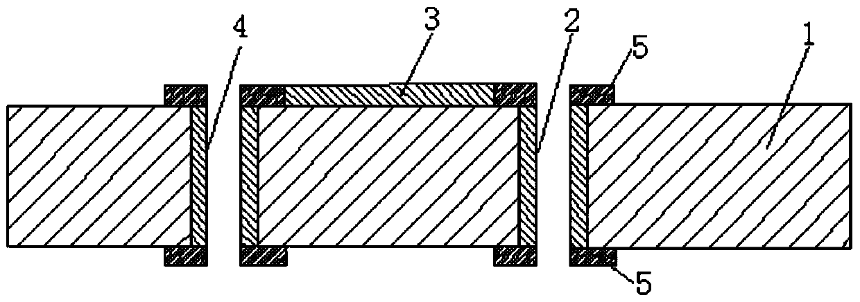
[0041] The test circuit board provided by this embodiment, such as figure 1 shown, including:
[0042] Circuit substrate 1, one or multiple bonded, including a base material and a metal circuit layer disposed on both surfaces of the base material;
[0043] Metallized via holes 2 are provided through each of the circuit substrates 1;
[0044] The test signal leads 3 are arranged on any surface of any one of the base materials, one end thereof is electrically connected to the metallized via hole 2 , and the other end thereof is electrically connected to a test point on the surface of the test circuit board.
[0045] When using the signal testing device to test the above-mentioned test circuit board, it is possible to realize the measurement of the signal between the metallized via hole 2 and the test signal lead 3, and between the two ends of the test signal lead 3, and through methods such as calibration The signal measurement value is analyzed and optimized, so as to obtain th...
Embodiment 2
[0058] This embodiment provides a method for manufacturing a test circuit board, comprising the following steps:
[0059] Make a double-sided substrate or a multilayer circuit substrate 1, the double-sided substrate includes a base material and metal layers disposed on both surfaces of the base material, the multilayer circuit substrate 1 is composed of at least two etched double-sided substrates Bonding is formed, and only the metal layer of the inner layer in the multilayer circuit substrate 1 is etched into an internal metal circuit layer;
[0060] Drilling through holes on the double-sided substrate or the multilayer circuit substrate 1 and plating metal in the through holes to obtain metallized via holes 2;
[0061] Etching the metal layer on the outer layer of the double-sided substrate or the multilayer circuit substrate 1 to form an outer metal circuit layer;
[0062] Wherein, in the step of forming the inner metal circuit layer or the outer metal circuit layer, the c...
Embodiment 3
[0069] This embodiment provides a test method, using a signal test device to test the metallized via hole 2 in the test circuit board provided by the embodiment of the present invention, the test method includes the following steps:
[0070] The test result calibration of the test signal lead 3 in the test circuit board is reset to zero by using the signal test device;
[0071] The signal test device is used to measure the signal between the metallized via hole 2 and the test signal lead 3 , and the measurement result is used as the signal value of the metallized via hole 2 .
[0072] It should be noted that, in the step of using the signal test device to calibrate and reset the test result of the test signal lead 3 in the test circuit board to zero, place the two test terminals of the signal test device at a and c independently, to figure 2 The test result of the test signal lead 3 on the left side of the center is calibrated and reset to zero, and the two test terminals of...
PUM
 Abstract
Description
Claims
Application Information
 - R&D
- Intellectual Property
- Life Sciences
- Materials
- Tech Scout
- Unparalleled Data Quality
- Higher Quality Content
- 60% Fewer Hallucinations
Browse by: Latest US Patents, China's latest patents, Technical Efficacy Thesaurus, Application Domain, Technology Topic, Popular Technical Reports.
© 2025 PatSnap. All rights reserved.Legal|Privacy policy|Modern Slavery Act Transparency Statement|Sitemap|About US| Contact US: help@patsnap.com


