
Configuring method of current equalizing resistor for direct current grounding electrode

A configuration method, DC grounding technology, applied in electrical digital data processing, special data processing applications, instruments, etc., can solve problems such as step voltage exceeding the standard, lower than the allowable value, and inability to implement, and achieves strong engineering applicability and cost. Inexpensive and reliable results

Active Publication Date: 2016-04-27
CHINA ELECTRIC POWER RES INST +1
View PDF6 Cites 6 Cited by
  • Summary
  • Abstract
  • Description
  • Claims
  • Application Information

AI Technical Summary

Problems solved by technology

The reasons for the above two aspects have caused enormous pressure on the step voltage design near the pole site. Simply relying on the method of increasing the size and buried depth of the pole ring not only costs a lot of money, but also sometimes cannot be implemented due to site constraints.
[0004] In addition, most DC ground electrodes are calculated using the ideal horizontal layered soil model during engineering design. In fact, due to the complexity and anisotropy of the soil resistivity distribution, the shielding effect between the pole ring conductors, and the existence of There are many uncontrollable factors, and the dispersion effect of each direction and each ring section of the DC grounding pole ring is often significantly different, resulting in an unbalanced distribution of the step voltage of the pole site. In the actual test, the step voltage of some areas often exceeds the standard, and the other part In the case where the step voltage in the area is much lower than the allowable value, the dispersion capacity of the entire pole ring has not been fully utilized

Method used


Image

  • Configuring method of current equalizing resistor for direct current grounding electrode

Examples


Embodiment Construction

[0036] The technical solution of the present invention will be further described in detail below in conjunction with the accompanying drawings and specific embodiments:

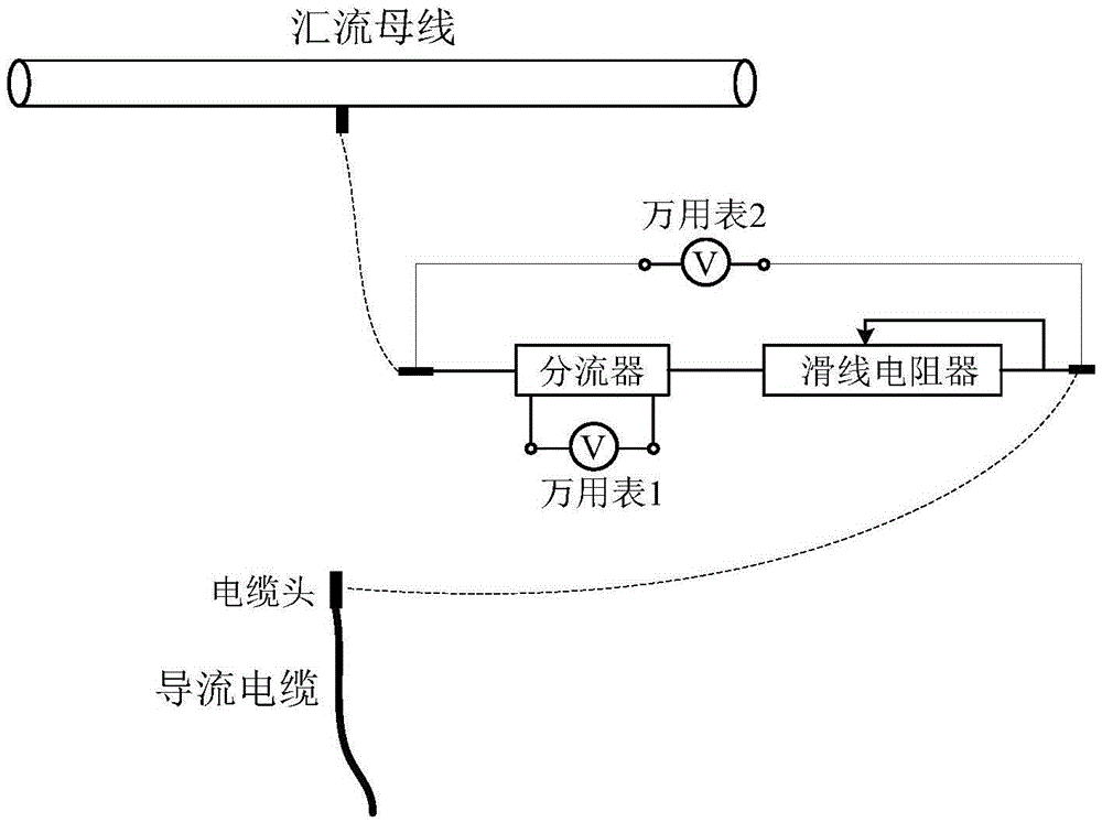
[0037] After the construction of the ground electrode is completed, the DC power supply is used for power supply, and the ground grid of the converter station, the ground electrode pole line and the ground electrode are used to form a test circuit, and a DC current of not less than 100A is injected into the ground electrode current and the current is kept constant. According to the segmentation of the design of the ground pole ring and the corresponding relationship between the guide cable and the ring section, the shunt value of each guide cable of the ground electrode, the ground resistance value of the ground electrode, the ground resistance value of each section of the pole ring, and the ring section are measured. The mutual resistance value between the segments, the step voltage coefficient of each segmen...


PUM


Abstract

The invention provides a configuring method of a current equalizing resistor for a direct current grounding electrode. The configuring method comprises the following steps of sequentially and serially connecting a direct current power source with a grounding net of a converter station, an electrode line and the grounding electrode; injecting current into the grounding electrode, and maintaining the constant current; measuring the electric parameters of the grounding electrode, and calculating the resistance of the current equalizing resistor; determining a configuring plan of the current equalizing resistor. The configuring method has the advantages that the implementing of the technical scheme is free from the limitation of terrain conditions, the excavation and reforming, the additional land reclamation, and the influence on surrounding environments; the construction is simple, the cost is low, and the reliability is high.

Description

technical field [0001] The invention relates to a DC grounding electrode current-sharing resistor, in particular to a configuration method for a DC grounding electrode current-sharing resistor. Background technique [0002] The grounding electrode is a conductive element buried in the ground. A good grounding electrode has the functions of lightning protection and disaster reduction and avoiding heavy losses in special natural environments. It provides protection for safe production and life, and is of great significance. After the huge DC current dissipates from the ground electrode, the constant current field in the earth will distribute the step voltage near the electrode site. If it exceeds the tolerance of the human body, it may endanger the personal safety of the personnel around the electrode site and cause a safety accident. [0003] As the site selection of DC grounding electrodes becomes more and more difficult, sometimes in order to fully avoid the impact on surro...

Claims


Application Information

Patent Timeline
Patent Type & Authority Applications(China)
IPC IPC(8): G06F17/50
CPCG06F30/367G06F30/398
Inventor 谭波董晓辉童雪芳王湘汉戴敏杨杰毕晟
Owner CHINA ELECTRIC POWER RES INST
Learn More