Rotor and motor

A rotor and rotor shaft technology, applied in the direction of magnetic circuit rotating parts, magnetic circuit shape/style/structure, etc., can solve problems such as defect, easy relative displacement, rotor drop test, etc., to reduce assembly difficulty, increase difficulty, Avoid or test the effect of undesirable phenomena

Active Publication Date: 2019-09-06
GREE ELECTRIC APPLIANCES INC +1
View PDF5 Cites 0 Cited by
  • Summary
  • Abstract
  • Description
  • Claims
  • Application Information

AI Technical Summary

Problems solved by technology

The rotor of the above-mentioned rotating electric machine restricts the relative rotation of the shaft and the core in the circumferential direction through the engagement of the engaging portion and the protruding line, but relative displacement easily occurs in the axial direction of the shaft and the core. resulting in a rotor drop or poor test

Method used


Image

  • Rotor and motor
  • Rotor and motor
  • Rotor and motor

Examples


Embodiment Construction

[0021] The present invention will be described in detail below in conjunction with examples. It should be noted that, in the case of no conflict, the embodiments in the present application and the features in the embodiments can be combined with each other.

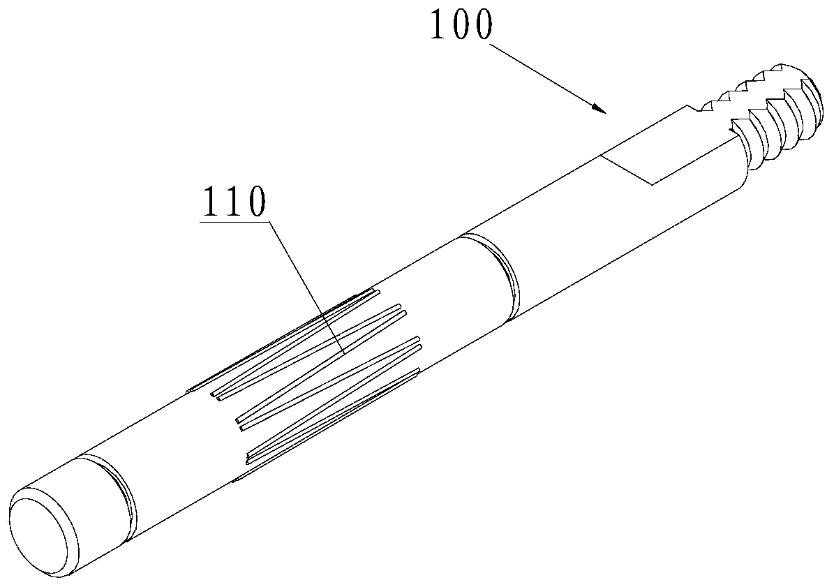
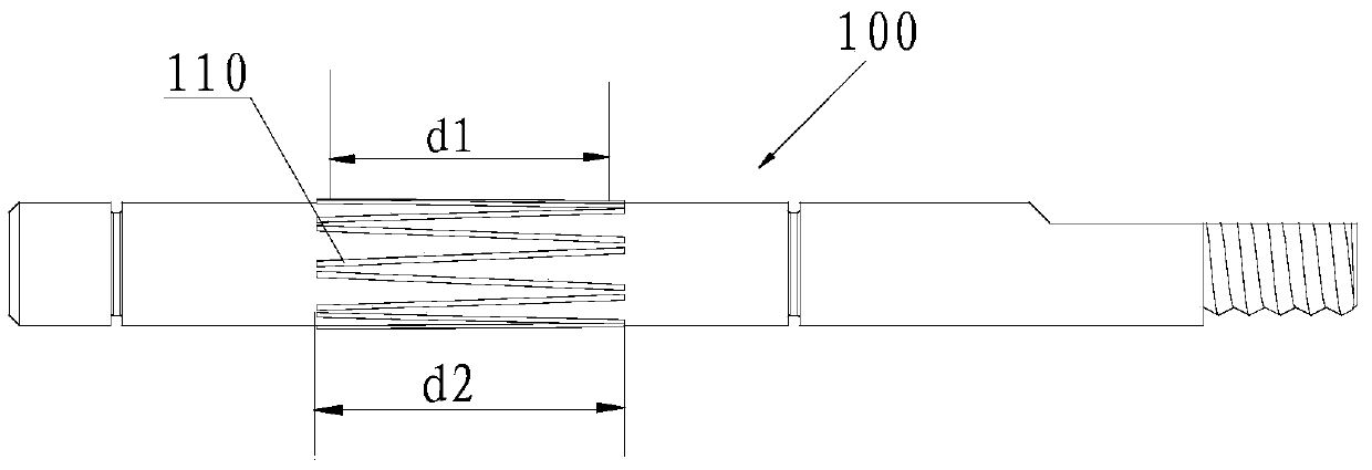
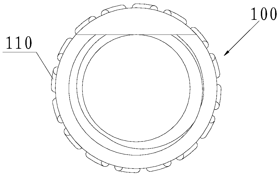
[0022] see Figure 1 to Figure 3 , the present invention provides a rotor, including a rotor core and a rotor shaft 100 sleeved in the rotor core. Wherein, a raised knurling 110 is provided on the area of ​​the rotor shaft 100 mated with the rotor core, and the raised knurling 110 is not parallel to the centerline (axis) of the rotor shaft 100 .

[0023] The rotor of the present invention is mainly improved on the rotor shaft 100. On the basis of the traditional rotor shaft, the rotor shaft 100 of the present invention is provided with raised knurling 110 on the area matching the rotor core, without increasing the rotor Under the premise that it is difficult for the shaft 100 to enter the iron core, the interference and...


PUM


Abstract

The invention discloses a rotor and a motor. The rotor comprises a rotor core and a rotor shaft (100), wherein the rotor shaft (100) is sleeved with the rotor core; a convex knurling (110) is arranged in a region, matched with the rotor core, of the rotor shaft (100); and the convex knurling (110) is not parallel to a center line of the rotor shaft (100). The convex knurling (110) is arranged on the rotor shaft (100); and the rotor shaft (100) is matched with the rotor core through the convex knurling (110), so that the defect caused by too high or too low magnitude of interference in the circumference fit process is avoided; the magnitude of interference between the rotor shaft (100) and the rotor core is increased under the premise of not increasing the difficulty that the rotor shaft (100) enters the rotor core; the difficulty of axial relative displacement of the rotor core and the rotor shaft (100) is increased; and falling of the rotor or the phenomenon of a poor test is effectively prevented.

Description

technical field [0001] The invention relates to the field of motors, in particular to a rotor and a motor including the rotor. Background technique [0002] At present, the matching method of the rotor shaft and the rotor core on the market is mainly an interference fit, and the rotor shaft is pressed into the shaft hole of the rotor core by cold pressing or shrink fitting. This fit method has the following disadvantages: if the design of the interference is too large, it will be very difficult or even impossible for the rotor shaft to enter the rotor core; if the design of the interference is too small, after the rotor shaft enters the rotor core, the two If the fit is not tight enough, there will be a large displacement between the rotor shaft and the rotor core, which will easily cause the rotor to drop or fail to test. [0003] Patent CN 102244424 A discloses a rotor of a rotating electrical machine, the rotor includes: a shaft, and a core body fitted on the outer perip...

Claims


Application Information

Patent Timeline
Patent Type & Authority Patents(China)
IPC IPC(8): H02K1/22
Inventor 黄男吴雨顺周成海刘丽刚陈鹤碧
Owner GREE ELECTRIC APPLIANCES INC
Why Eureka
Try Eureka