


Quick Research
Generate reliable direction feasibility study reports for your R&D in just a few steps.

Technical Q&A
Discover and master advanced knowledge NOW. Basics, ideas, possibilities, all at once.

Find Solutions
As an expert in R&D theories, this can generate solutions to your technical problems instantly.

Evaluate Feasibility
Analyze your overall solution with one click, know your potential R&D risks in advance.

Monitor Landscape
Get weekly tech updates, stay abreast of the latest tech innovations and key insights.
Linear vibration motor
A linear vibration and motor technology, applied in the direction of electromechanical devices, electrical components, etc., can solve the problems of changes in the force of the vibrator, large vibration sense, slow system response, etc., to achieve the effect of shortening time and large vibration sense
- Summary
- Abstract
- Description
- Claims
- Application Information
AI Technical Summary
Problems solved by technology
Method used
Image

Examples
Embodiment 2
[0054] Figure 4 It is the cross-sectional structure of the linear vibration motor according to the second embodiment of the present invention; Figure 5-1 and Figure 5-2 They are the principle structures of the linear vibration motor in the static state and the vibration state according to the second embodiment of the present invention, respectively.
[0055] exist Figure 4 to Figure 5-2 In the second embodiment shown, the magnetic permeable blocks are arranged asymmetrically on the upper and lower sides of the central vibrating block; and the magnetic permeable blocks asymmetrically arranged on the upper and lower sides of the central vibrating block are symmetrical to the center of the central vibrating block.
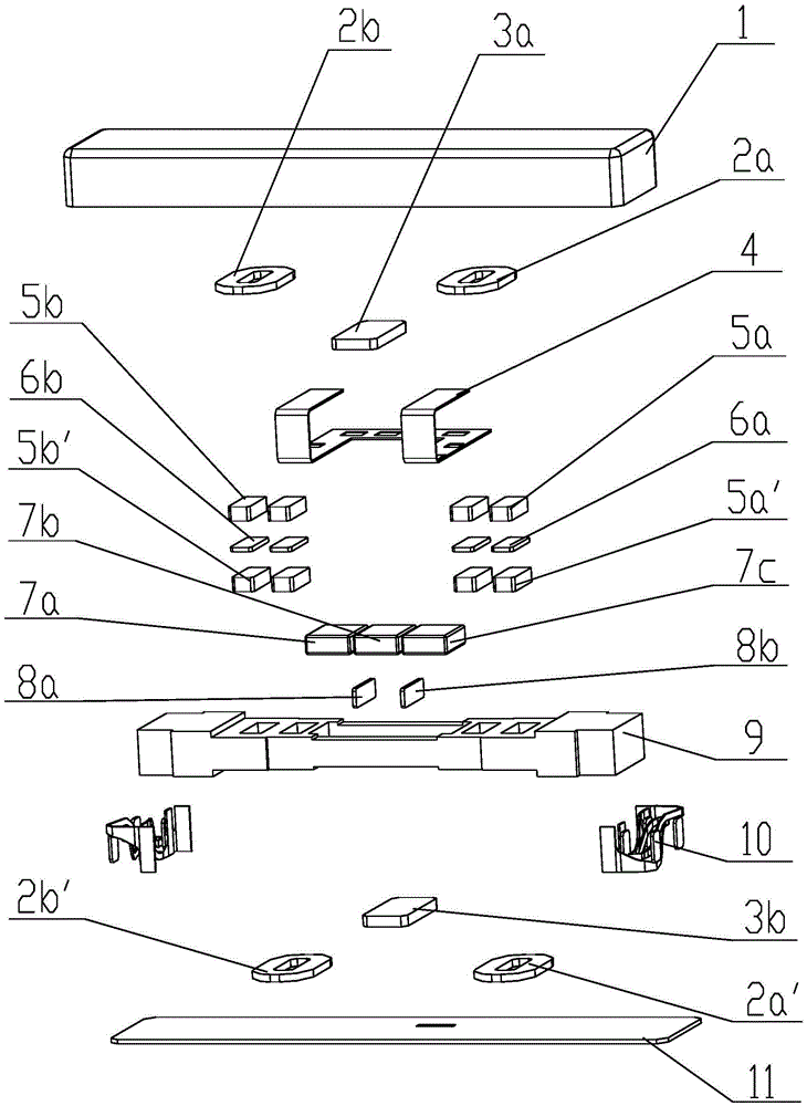
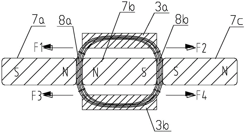
[0056] Wherein, the central vibrating block comprises three adjacent first permanent magnets 7a, second permanent magnets 7b and third permanent magnets 7c, the three adjacent permanent magnets are all magnetized in the horizontal direction, and the adjacent Ad...
Embodiment 3
[0060] Figure 6 It is the cross-sectional structure of the linear vibration motor according to the third embodiment of the present invention; Figure 7-1 and Figure 7-2 They are respectively the principle structure of the static state and the vibration state of the linear vibration motor according to the third embodiment of the present invention.
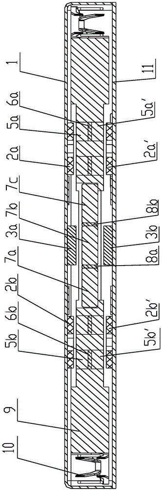
[0061] exist Figure 6 to Figure 7-1 In the third embodiment shown, in order to increase the magnetic permeability of the magnetic permeable block and increase the vibration amplitude of the vibrator, six magnetic permeable blocks are arranged symmetrically on the upper and lower sides of the three adjacent permanent magnets, namely , the upper and lower sides of each permanent magnet of the central vibration block are provided with magnetic conductive blocks.
[0062] Wherein, the central vibrating block comprises three adjacent first permanent magnets 7a, second permanent magnets 7b and third permanent magnets 7c, the three a...
Embodiment 4
[0065] Figure 8 It is the cross-sectional structure of the linear vibration motor according to Embodiment 4 of the present invention; Figure 8-1 and Figure 8-2 They are respectively the principle structure of the linear vibration motor in the static state and the vibration state according to the fourth embodiment of the present invention.
[0066] Such as Figure 8 to Figure 8-2 In the fourth embodiment shown, a magnetic gap is formed between the magnetic permeable block and the permanent magnet of the corresponding vibrating block, and a magnetic fluid 12 is arranged in the magnetic gap. Wherein, a magnetic gap is formed between the vibrator and the magnetic block, and a flexible magnetic member is filled in the magnetic gap, and the flexible magnetic member can be a magnetic fluid 12, wherein the magnetic fluid 12 is a colloidal substance with magnetism, Mainly refers to nano-scale magnetic particles (nickel, cobalt, iron oxide, etc.) coated with long-chain surfactants...
PUM
 Abstract
Description
Claims
Application Information
 - R&D Engineer
- R&D Manager
- IP Professional
- Industry Leading Data Capabilities
- Powerful AI technology
- Patent DNA Extraction
Browse by: Latest US Patents, China's latest patents, Technical Efficacy Thesaurus, Application Domain, Technology Topic, Popular Technical Reports.
© 2024 PatSnap. All rights reserved.Legal|Privacy policy|Modern Slavery Act Transparency Statement|Sitemap|About US| Contact US: help@patsnap.com