
Channel Dynamic Allocation Method Based on Captain Prediction

A dynamic allocation and channel technology, applied in wireless communication, electrical components, etc., can solve the problems that cannot reflect the business needs of nodes, affect the accuracy of channel allocation, and do not consider the amount of data, so as to achieve accurate actual business needs and improve channel utilization. , the effect of improving accuracy

Active Publication Date: 2018-11-16
XIDIAN UNIV
View PDF5 Cites 0 Cited by
  • Summary
  • Abstract
  • Description
  • Claims
  • Application Information

AI Technical Summary

Problems solved by technology

Because in this report / authorization-based channel allocation method, there is a certain delay between the calculation time of the channel allocation scheme or the captain report time and the start time of data transmission, and this method does not consider the data entering the node queue during this period Therefore, it cannot reflect the actual business needs of the nodes, which affects the accuracy of channel allocation and reduces the channel utilization

Method used


Image

  • Channel Dynamic Allocation Method Based on Captain Prediction
  • Channel Dynamic Allocation Method Based on Captain Prediction
  • Channel Dynamic Allocation Method Based on Captain Prediction

Examples


Embodiment Construction

[0038] The content of the present invention will be further elaborated below in conjunction with the accompanying drawings.

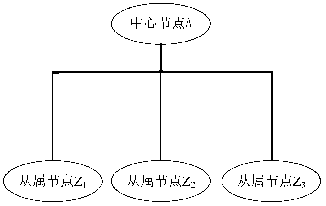
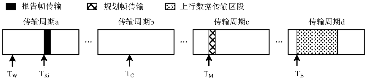
[0039] refer to figure 1 , the network used in this example consists of a central node A and P = 3 slave nodes, and the slave node number is Z i , i=1~P. The channel in the network is divided into continuous and non-overlapping transmission periods, where transmission period a, transmission period b, transmission period c, and transmission period d are four consecutive transmission periods, and the length of each transmission period is 2.3ms. The length of the uplink data transmission segment is 0.8 ms, and the length of the downlink data transmission segment is 1 ms.

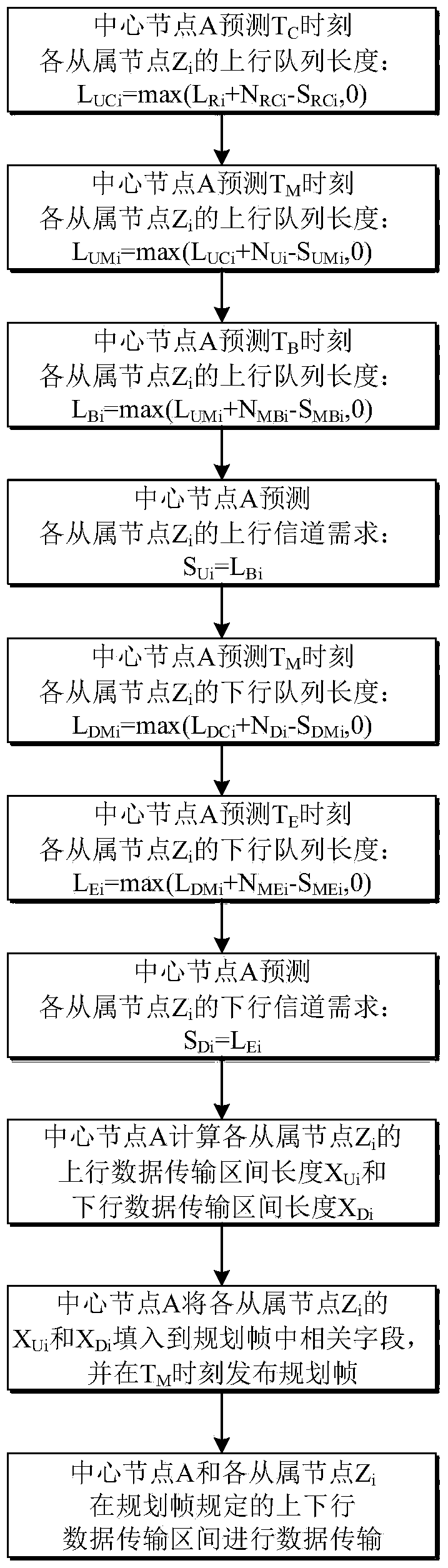
[0040] refer to figure 2 , the implementation steps of this example are as follows:

[0041] Step 1, get working hours:

[0042] refer to image 3 , in the transmission period a, the slave node Z i The time to start recording the amount of data entering its upstream queue is T W...


PUM


Abstract

The invention discloses a channel dynamic allocation method based on captain prediction, which mainly solves the problem that the channel resource allocation results in the existing time division duplex / time division multiple access channel allocation methods cannot reflect the actual service needs of nodes and the channel utilization rate cannot meet the requirements . The technical solution is: assume that there is a central node and several subordinate nodes in the network, and divide the channel into continuous and non-overlapping transmission periods; each subordinate node reports its uplink queue length to the central node, and the central node obtains the Downlink queue length; based on this, the central node predicts the uplink and downlink channel requirements of each slave node, and then uses the scheduling algorithm to calculate the length of the uplink and downlink data transmission interval of each slave node, and fills it into the relevant fields in the planning frame; the central node specifies Publish planning frames at all times. The invention can more accurately predict the actual service demand of the nodes, improves the channel utilization rate, and can be applied to various communication local area networks and access network fields.

Description

technical field [0001] The invention belongs to the technical field of communication, and relates to a channel dynamic allocation method, which can be applied to various communication local area networks and access network fields. Background technique [0002] In LANs and access networks based on shared media, in order to achieve reasonable and conflict-free allocation of channel resources, a central point-to-multipoint logical topology is often used. In this network structure, the central node uniformly allocates channel resources for the remaining slave nodes. Data communication can be carried out directly between the central node and the slave nodes. Generally, the transmission from the slave node to the central node is called uplink transmission, and the transmission from the central node to the slave node is called downlink transmission. [0003] In broadcast channels for point-to-multipoint communication, in order to provide quality of service (QoS) guarantees, the c...

Claims


Application Information

Patent Timeline
Patent Type & Authority Patents(China)
IPC IPC(8): H04W72/04H04W72/12
CPCH04W72/0446H04W72/52
Inventor 张奭姜思捷张冰姜逸坤张宇罗佳韵陈添财段江鹏杜滨源
Owner XIDIAN UNIV
Learn More