
Waterproof control unit and method of assembling the same

A control unit, waterproof technology, used in coupling devices, electrical components, printed circuit manufacturing, etc., can solve the problems of inability to assemble for use, deep convex and concave surfaces, difficult to form, etc., to improve waterproof performance, prevent peeling, and improve deformation. the effect of strength

Active Publication Date: 2016-04-27
MITSUBISHI ELECTRIC CORP
View PDF6 Cites 4 Cited by
  • Summary
  • Abstract
  • Description
  • Claims
  • Application Information

AI Technical Summary

Problems solved by technology

[0004] On the other hand, the disadvantage of the convex-concave sealing surface method is that if the fitting depth is increased in proportion to the sealing width of the convex-concave sealing surface in order to ensure the sealing path, it will be obtained after cold-pressing an inexpensive metal plate, for example. It is difficult to form narrow and deep fine convex and concave surfaces in the outer shell and base
[0005] Therefore, for the connector case in which contact terminals with complex shapes are press-fitted, due to the thermocompression molding process using a resin material, a fine convex-concave sealing surface may be formed, but the above-mentioned connector with a fine convex-concave sealing surface The box body cannot be assembled with an inexpensive metal plate case or base, and even the base and case must use parts obtained by, for example, aluminum alloy die-casting or thermocompression molding of a resin material.
[0006] Therefore, when trying to apply an inexpensive metal plate housing or base, there is a problem that different types of connector boxes must be manufactured using different molds.

Method used


Image

  • Waterproof control unit and method of assembling the same
  • Waterproof control unit and method of assembling the same
  • Waterproof control unit and method of assembling the same

Examples


Embodiment approach 1

[0095] (1) Detailed description of the structure

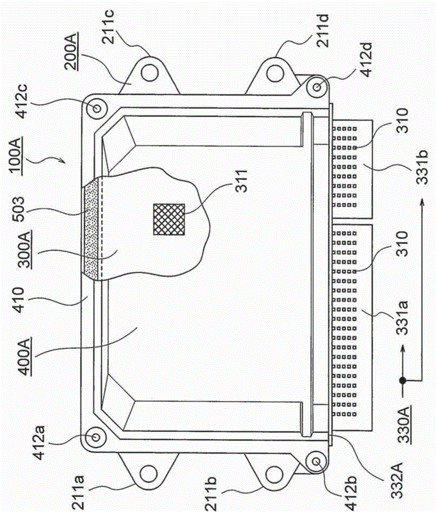
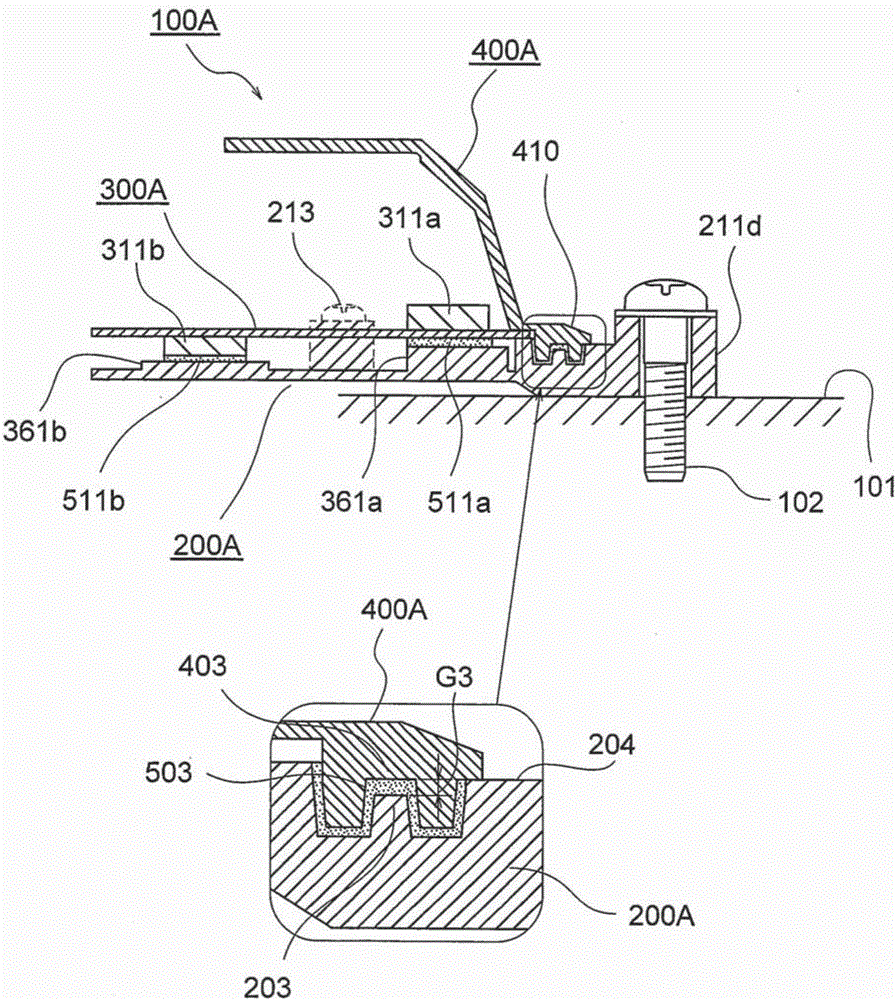
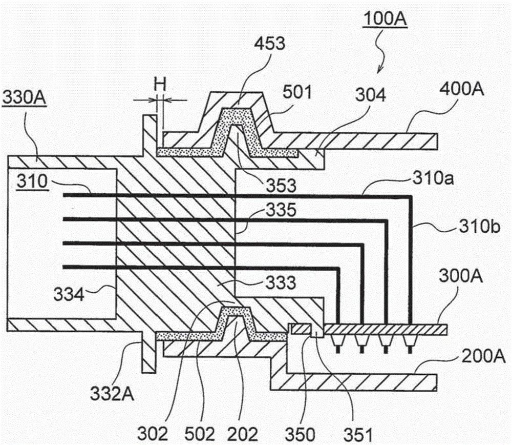
[0096] First, in order figure 1 , figure 2 , image 3 , Figure 4A ~ Figure 4C ,as well as Figure 5 , figure 1 is an external view of a waterproof control unit according to Embodiment 1 of the present invention, figure 2 yes figure 1 The installation structure diagram of the waterproof control unit, image 3 yes figure 1 A detailed cross-sectional view of the connector box, Figure 4A ~ Figure 4C yes image 3 A more detailed cross-sectional view of the connector box, Figure 5 is along Figure 4A A cross-sectional view of the connector box observed on the D-D line.

[0097] exist figure 1 Among them, the waterproof control unit 100A includes: a base 200A made of aluminum alloy die-casting having mounting feet 211a to 211d at four corners; a circuit board 300A loaded with a plurality of circuit devices 311 and heating devices 311a and 311b described later; And the resin housing 400A having edge-shaped flanges...

Embodiment approach 2

[0215] (1) Detailed description of the structure

[0216] Next, the top view of the waterproof control unit according to Embodiment 2 of the present invention is Figure 10 , Figure 10 The side partial sectional view of the waterproof control unit is Figure 11 , Figure 10 A detailed cross-sectional view of the connector box viz. Figure 12 , Figure 12 A more detailed cross-sectional view of the connector box is Figure 13A ~ Figure 13C , and will be along Figure 13A The cross-sectional view observed on the D-D line of the connector box is turned upside down and the figure is Figure 14 , with Figure 1 to Figure 5 Focusing on the differences, we will describe in detail.

[0217] In addition, the same code|symbol in each figure shows the same or corresponding part.

[0218] Figure 10 Among them, the waterproof control unit 100B includes: a base 200B made of metal plate having mounting feet 211B, 211B on the left and right; The shell 400B made of a metal plate h...

Embodiment approach 3

[0302] (1) Detailed description of the structure

[0303] Next, the rear appearance view of the waterproof control unit according to Embodiment 3 of the present invention is Figure 18 , Figure 18 The partial cross-sectional side view of the waterproof control unit is Figure 19 , Figure 18 A detailed cross-sectional view of the connector box viz. Figure 20 , Figure 18 A more detailed cross-sectional view of the connector box is Figure 21A ~ Figure 21C , with Figure 1 to Figure 5 Focusing on the differences, we will describe in detail. In addition, the same code|symbol in each figure shows the same or corresponding part.

[0304] exist Figure 18 Among them, the waterproof control unit 100C includes: a base 200C made of aluminum alloy die-casting having mounting feet 211a-211d at four corners; Figure 19 A plurality of circuit components 311 shown, a circuit board 300C of heat generating components 311a and 311b described later, and a case 400C made of a metal p...


PUM


Abstract

In a waterproof control unit in which a part of a connector housing mounted on a circuit board is exposed and the circuit board is hermetically housed in a casing including a base and a cover, a sealing gap between the cover and the connector housing is defined between fitting surfaces of a first concave thread and a first convex thread, and a waterproof sealing material is applied to the sealing gap. A waterproof sealing material is applied to the latter sealing gap. Each of the sealing gaps extends inward and outward across an inner boundary surface of a partition wall of the connector housing. Plane movement of each of the sealing gaps is restricted by side-surface convex threads and side-surface concave threads.

Description

technical field [0001] The present invention relates to an improvement of an on-vehicle electronic control device, that is, a waterproof control unit and an assembly method thereof, which are installed in, for example, an engine room. Background technique [0002] The widely used waterproof control unit includes: a case composed of a base and a case; and a circuit board hermetically accommodated in the case, on which circuit devices and a plurality of contact terminals for external connection are mounted , and the circuit substrate is positioned and fixed with a resin molding material, that is, a connector box, and in order to expose the end surface of the connector box through which a plurality of contact terminals penetrate from the box, the waterproof control unit also has a waterproof sealing material , the waterproof sealing material is filled into the first sealing gap provided on the abutting surface of the connector box body and the shell, the second sealing gap prov...

Claims


Application Information

Patent Timeline
Patent Type & Authority Applications(China)
IPC IPC(8): H05K5/06
CPCH05K5/062H01R13/5202H05K3/28H05K3/341H05K5/0056H05K7/20445
Inventor 涂家伸朗西田充孝
Owner MITSUBISHI ELECTRIC CORP
Learn More