Sewage treatment plants and sewage lifting systems

A sewage treatment device and sewage treatment equipment technology, applied in chemical instruments and methods, filtration and separation, fixed filter element filters, etc., can solve the problems of high land acquisition and civil construction costs, high operating costs, easy wear and blockage of pumps, etc., to achieve The effect of reducing land acquisition and civil construction costs, reducing equipment costs, and avoiding blockage

Active Publication Date: 2017-12-19
WILO CHINA
View PDF6 Cites 0 Cited by
  • Summary
  • Abstract
  • Description
  • Claims
  • Application Information

AI Technical Summary

Problems solved by technology

Due to the large area occupied by the traditional wet concrete sewage pumping station, the cost of land acquisition and civil construction is high; it is necessary to add a large cast iron copper-embedded gate and hoist, a rotary grille and a screening conveyor, and the equipment cost is high; it requires a person on duty to clean the screening , high labor costs; low pump efficiency, high operating costs
Due to the poor working conditions, the pump is easy to wear and block, the failure rate is high, and the maintenance cost is high. In recent years, it has been used less and less in recent years. It has been replaced by an integrated wet prefabricated pump station.
The integrated wet prefabricated pump station adopts the characteristics of prefabricated shaft, crushed grid, and automatic control, which solves the shortcomings of high cost of land acquisition and civil engineering, and the need for people to be on duty. However, it still has high equipment costs, low pump station efficiency, and pumps are easy to wear and block. shortcoming

Method used


Image

  • Sewage treatment plants and sewage lifting systems
  • Sewage treatment plants and sewage lifting systems
  • Sewage treatment plants and sewage lifting systems

Examples


Embodiment Construction

[0029] The technical solutions of the present invention will be described in further detail below with reference to the accompanying drawings and embodiments.

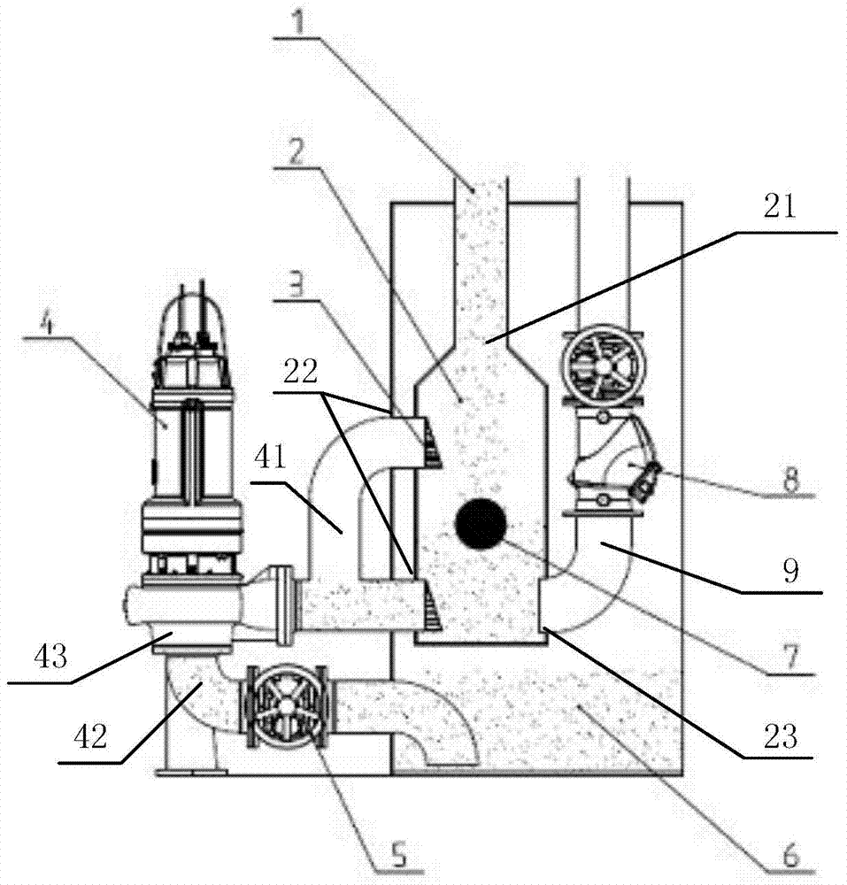
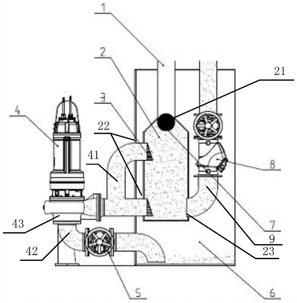
[0030] figure 1 The schematic diagram of the sewage treatment device provided for the embodiment of the present invention, as shown in the figure, the sewage treatment device includes: a water inlet pipe 1, a solid-liquid separation tank 2, a one-way filter 3, a cut-off float 7, a water collection tank 6, a sewage Pump 4 and outlet pipe 9;

[0031] The solid-liquid separation tank 2 has a water inlet 21, a filtered water outlet 22 and a sewage outlet 23;

[0032] Wherein, the water inlet 21 is arranged on the top of the solid-liquid separation tank 2, and is connected with the water inlet pipe 1;

[0033] There are one or more filter outlets 22, and at least one filter outlet 22 is arranged at the bottom of the solid-liquid separation tank 2, so that the sewage in the solid-liquid separation tank 2 can be drained as ...


PUM


Abstract

The embodiment of the present invention relates to a sewage treatment device and a sewage lifting system. The sewage treatment device includes: a water inlet pipe, a solid-liquid separation tank, a one-way filter, a cut-off float, a water collection tank, a sewage pump and a water outlet pipe; solid-liquid separation The tank has a water inlet, a filtered water outlet and a sewage outlet; the sewage pump includes a pump body, a first connecting pipe and a second connecting pipe; the first connecting pipe is respectively connected to the one-way filter and the pump body; the second connecting pipe is connected to the pump When collecting water, the sewage flows into the solid-liquid separation tank from the water inlet pipe, and after being filtered by the one-way filter, the liquid part passes through the sewage outlet, the first connecting pipe, the pump body and the second connecting pipe into the water collection tank; the solid residue in the sewage is filtered by the one-way filter in the solid-liquid separation tank; when draining, the sewage pump starts to work, and the sewage in the water collection tank is pumped out by the second connecting pipe, pump body, The first connecting pipe and the one-way filter enter the water collection tank, and then are discharged from the outlet pipe through the sewage outlet.

Description

technical field [0001] The invention relates to the field of sewage treatment, in particular to a sewage treatment device and a sewage lifting system. Background technique [0002] The sewage pumping station is a pumping station installed in the sewage pipeline system to pump up urban sewage. Because the sewage pipe is not like the water supply pipe (tap water), it has no pressure and needs to rely on the gravity of the sewage itself. Since the sewage collected by the urban sewage interception network pipe has a large area and is far away from the sewage treatment plant, it is impossible to bury the pipe It is very deep, so pumping stations need to be set up to raise the elevation of the sewage. Among them, the maximum particle passing rate and the energy efficiency level of the pumping station are important parameters of the sewage pumping station. In the environment where the country advocates energy conservation and emission reduction, it is of great practical significa...

Claims


Application Information

Patent Timeline
Patent Type & Authority Patents(China)
IPC IPC(8): B01D29/00
CPCB01D29/88
Inventor 滕人博李平洲张建文
Owner WILO CHINA
Why Eureka
Try Eureka