
An Automatic Clamp Mechanism for a CNC Punch Machine

A CNC punching and automatic technology, applied in metal processing equipment, feeding devices, manufacturing tools, etc., can solve the problems of automatic loosening of the clamping mechanism, inability to monitor data, and inability to automatically lock, and achieve reliable clamping functions. Effect

Active Publication Date: 2018-04-03
爱克(苏州)机械有限公司
View PDF7 Cites 0 Cited by
  • Summary
  • Abstract
  • Description
  • Claims
  • Application Information

AI Technical Summary

Problems solved by technology

Among them, the structure of the clamp is one of the important reasons that affect the precision of the processed parts. Control the clamp body and the left and right guide arms to reduce the swing range after the force is applied. Automatic locking to meet faster and more efficient operation; and the existing clamping mechanism will be affected by air source fluctuations, air pressure and power failure, so that the clamping mechanism will automatically loosen; moreover, the existing clamping mechanism is in the During use, it does not have the function of real-time monitoring, cannot monitor the data, and perform safety interlocking to ensure safety

Method used


Image

  • An Automatic Clamp Mechanism for a CNC Punch Machine
  • An Automatic Clamp Mechanism for a CNC Punch Machine

Examples


Embodiment Construction

[0012] The following will clearly and completely describe the technical solutions in the embodiments of the present invention with reference to the accompanying drawings in the embodiments of the present invention. Obviously, the described embodiments are only some, not all, embodiments of the present invention. Based on the embodiments of the present invention, all other embodiments obtained by persons of ordinary skill in the art without making creative efforts belong to the protection scope of the present invention.

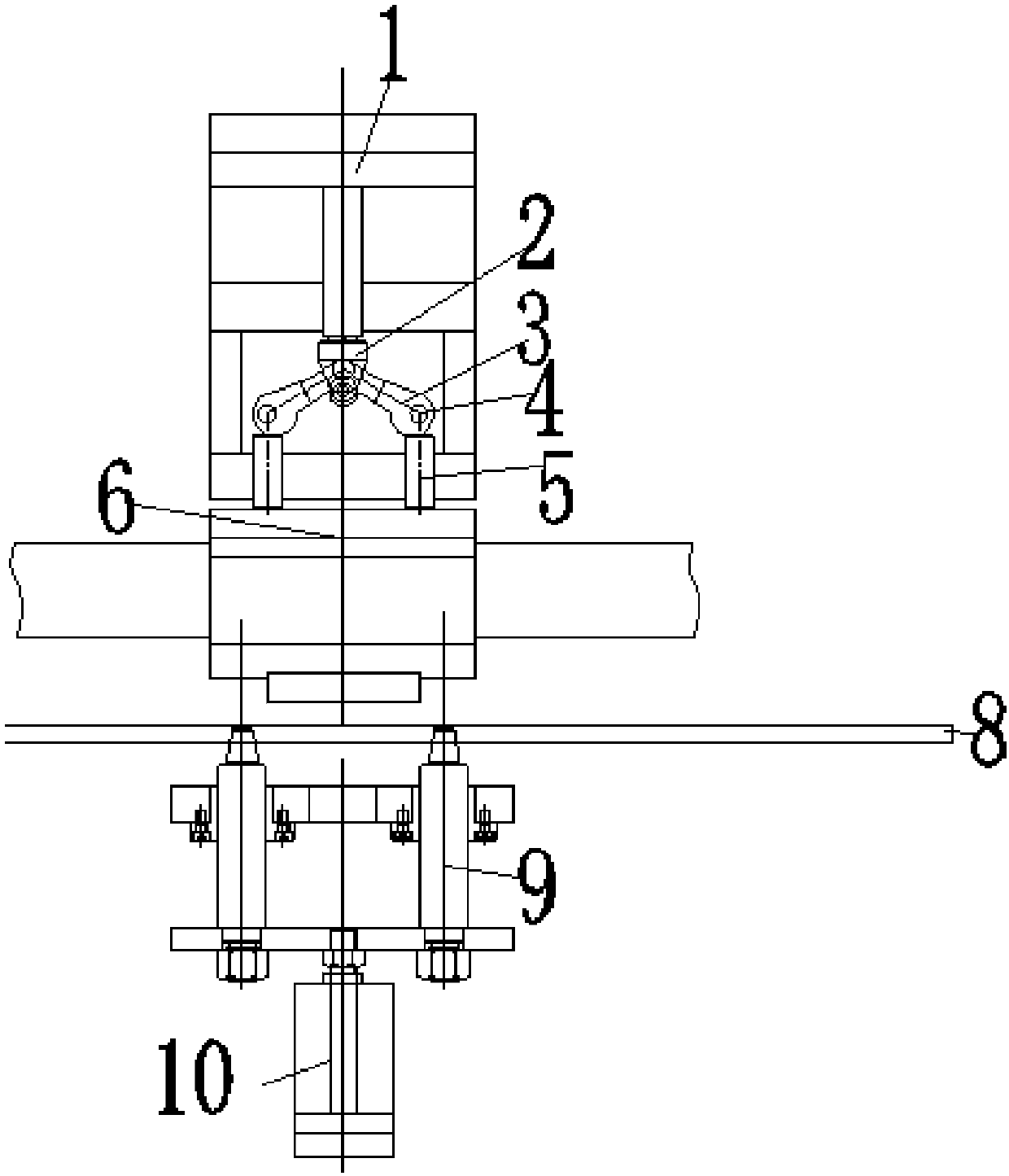
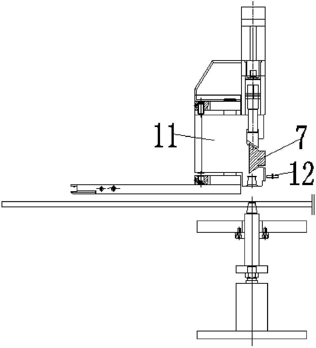
[0013] see Figure 1-2 , the present invention provides a technical solution: an automatic clamping mechanism for a CNC punch press, including a locking cylinder 1, a connecting plate 2, a punch table 8 and a positioning cylinder 10, and the connecting plate 2 is arranged at the center of the bottom of the locking cylinder 1 Position, the connecting plate 2 is vertically arranged above the punch table 8, the positioning cylinder 10 is located directly below th...


PUM


Abstract

The invention discloses an automatic clamp tong mechanism of a numerically-controlled punch press. The automatic clamp tong mechanism comprises a locking air cylinder, a connecting plate, a punch press table top and a positioning air cylinder; the top end of the bottom of the connecting plate is connected with two cam crank arms which are symmetrically arranged, a camshaft is arranged at the bottom of each cam crank arm, each camshaft is connected with a push rod, a locking plate is arranged under the push rods and slidably connected to the side wall of a dovetail-shaped slide rail, and the locking plate and the dovetail-shaped slide rail are both located over the punch press table top; the punch press table top and the positioning air cylinder are connected through two positioning pins, the positioning pins fix a clamp tong body in a clamping mode, and a position sensor is arranged at the edge of the punch press table top and electrically connected with the dovetail-shaped slide rail. According to the clamp tong mechanism, the clamping function of a double-cam push rod clamp tong is reliable, and a self-locking function is achieved; the phenomenon that the clamp tong is loosened due to the fact that an air source fluctuates, loses voltage and loses power cannot occur; meanwhile, real-time monitoring is performed through the position sensor, and then safety interlocking of electric appliances is achieved.

Description

technical field [0001] The invention relates to the technical field of numerical control punching equipment, in particular to an automatic clamping mechanism for a numerical control punching machine. Background technique [0002] The CNC punch press is equipped with a program control system, which can logically process programs with control codes or other symbolic instructions, and decode them, so that the punch press can move and process parts. Among them, the structure of the clamp is one of the important reasons that affect the precision of the processed parts. Control the clamp body and the left and right guide arms to reduce the swing range after the force is applied. Automatic locking to meet faster and more efficient operation; and the existing clamping mechanism will be affected by air source fluctuations, air pressure and power failure, so that the clamping mechanism will automatically loosen; moreover, the existing clamping mechanism is in the During use, it does ...

Claims


Application Information

Patent Timeline
Patent Type & Authority Patents(China)
IPC IPC(8): B21D43/11
CPCB21D43/11
Inventor 蔡国华沙晓慧吴凤江周锋
Owner 爱克(苏州)机械有限公司
Learn More