
Efficient electric automobile cooling system

A technology for electric vehicles and cooling systems, which is applied to the combined arrangement of cooling of power units, electric power units, power units, etc., can solve the problems of limited cooling efficiency of the cooling system, reduced operating efficiency, waste of electricity, etc., and achieves a cooling control method Flexible and diverse, strong cooling performance, the effect of high cooling performance

Active Publication Date: 2016-05-04
FJ MOTOR GRP YUDO NEW ENERGY AUTOMOBILE CO LTD
View PDF5 Cites 8 Cited by
  • Summary
  • Abstract
  • Description
  • Claims
  • Application Information

AI Technical Summary

Problems solved by technology

[0004] No matter which pipeline arrangement is adopted, the system flow rate remains the same, and the heat dissipation capacity of the system is constant, which cannot be adjusted according to the temperature of the components.
When the temperature of the motor etc. rises, its operating efficiency is reduced; when the temperature of the motor etc. decreases, the water pump always runs at high power, wasting too much electricity
[0005] Moreover, the cooling efficiency of the existing electric vehicle cooling system is limited, and it is impossible to cool down the high-power heating device in a timely and effective manner during high temperature or extreme driving in summer, which affects the performance and service life of the electric vehicle

Method used


Image

  • Efficient electric automobile cooling system
  • Efficient electric automobile cooling system
  • Efficient electric automobile cooling system

Examples


Embodiment Construction

[0035] In order to describe in detail the technical content, structural features, achieved objectives and effects of the present invention, the following is a detailed description in conjunction with the embodiments and accompanying drawings.

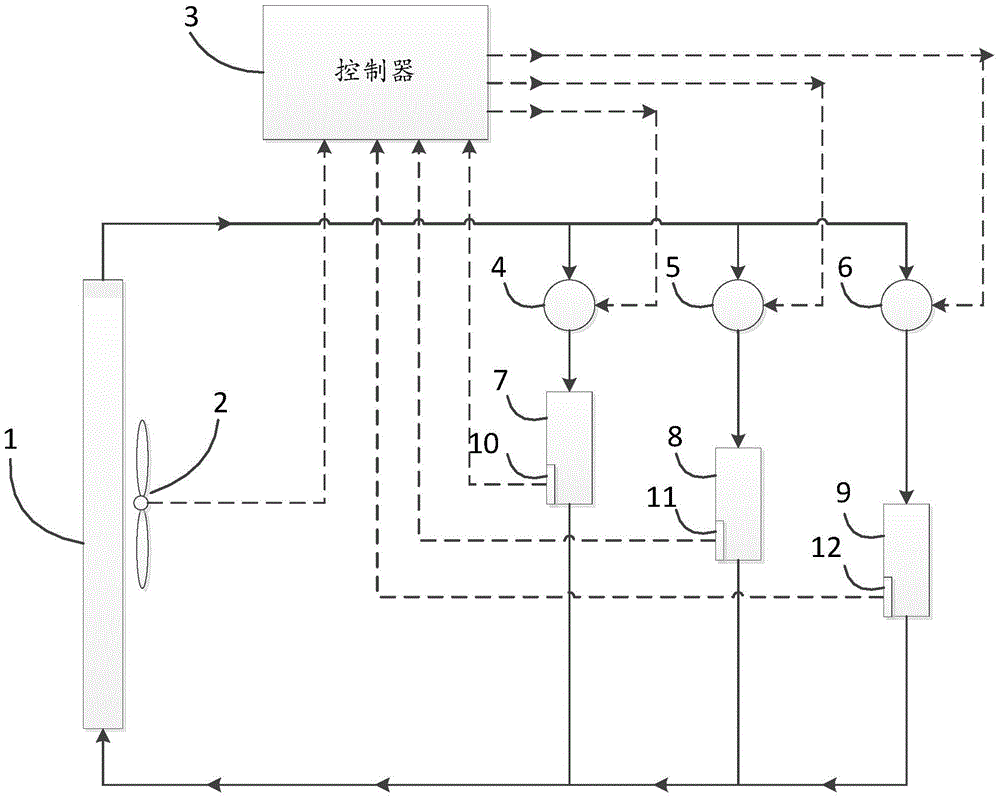
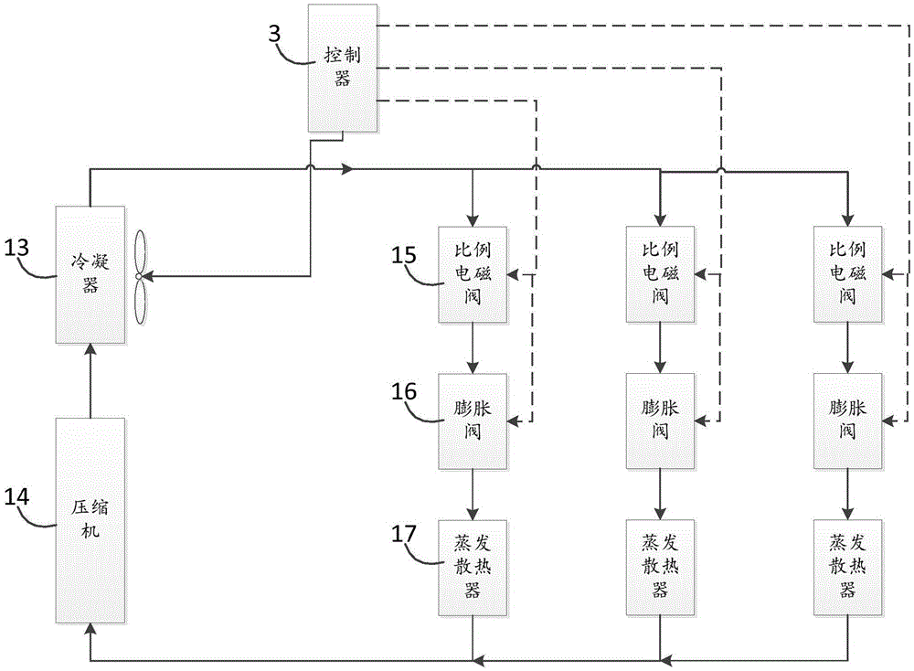
[0036] See figure 1 with figure 2 , Is a schematic diagram of the module connection of a water cooling device and a compression cooling device in an electric vehicle cooling system according to an embodiment of the present invention. The electric vehicle cooling system includes two sets of cooling devices, namely, a water cooling device (such as figure 1 Shown) and a compression cooling device (such as figure 2 Shown), and a cooling controller used to control the entire cooling process. The cooling control device includes a controller and a plurality of temperature sensors, namely figure 1 In 10, 11, and 12, the temperature sensor is used to collect the temperature of the heating device of the electric vehicle; the water cooling device use...


PUM


Abstract

The invention discloses an efficient electric automobile cooling system which comprises a cooling control device, a water cooling device and a compression cooling device. The cooling control device comprises a controller and multiple temperature sensors. The water cooling device comprises a cooling water radiator, a cooling water cooling fan and two or more water cooling branches. The water cooling branches are composed of water pumps and water cooling radiators, wherein the water pumps and the water cooling radiators are sequentially connected in series. The compression cooling device comprises a compressor, a condenser and two or more evaporation branches. The evaporation branches are composed of proportional electromagnetic valves, expansion valves and evaporation radiators, wherein the proportional electromagnetic valves, the expansion valves and the evaporation radiators are sequentially connected in series. The water cooling radiators and the evaporation radiators are connected with large-power heating devices of an electric automobile. The temperature sensors are used for detecting the temperatures of the large-power heating devices of the electric automobile. The temperature sensors, the water pumps, the compressor and the proportional electromagnetic valves are connected to the controller. The efficient electric automobile cooling system is good in cooling performance and low in power consumption.

Description

Technical field [0001] The invention relates to the field of electric vehicles, in particular to an efficient cooling system for electric vehicles. Background technique [0002] Electric vehicles use motors as direct power sources. During driving, the drive motors, controllers, and voltage conversion modules (ie DCDC modules) of electric vehicles will generate a lot of heat. In order to ensure the performance of electric vehicles, systems such as motors are required. Cool down. [0003] At present, the driving motors and their controllers, DCDC modules of electric vehicles are mainly cooled by water circulation. Existing water cooling systems generally use a radiator and a water pump to connect motors and motor controllers in series or in parallel for cooling. [0004] No matter which piping arrangement is adopted, the system flow rate remains the same, and the heat dissipation capacity of the system is constant and cannot be adjusted according to the temperature of the components....

Claims


Application Information

Patent Timeline
IPC IPC(8): B60K11/04B60K11/06B60K1/00
CPCB60K1/00B60K11/04B60K11/06B60K2001/006
Inventor 石凯凯林弟刘心文吴贵新徐辉
Owner FJ MOTOR GRP YUDO NEW ENERGY AUTOMOBILE CO LTD
Learn More