
High-power radio frequency surge protector and overheating protection method

A surge protector, high-power technology, used in emergency protection circuit devices, protection against overvoltage, emergency protection circuit devices for limiting overcurrent/overvoltage, etc. Heat sink structure, excessive capacitance value, burning discharge tube, etc., to avoid signal leakage, strong heat dissipation performance, and not easy to rust

Active Publication Date: 2015-08-05
ZHUZHOU PUTIAN ZHONGPU LIGHTNING PROTECTION TECH
View PDF4 Cites 0 Cited by
  • Summary
  • Abstract
  • Description
  • Claims
  • Application Information

AI Technical Summary

Problems solved by technology

[0009] Although the above two patents are related to the lightning protection device, but because they do not have the air guide groove and heat sink structure in the present invention, they cannot dissipate heat well, and are not suitable for high-power radio frequency systems with large heat generation. middle
In addition, in the above two patents, only the discharge tube is used to separate the inner conductor from the outer casing. Under the high voltage in the high-power radio frequency system, if the generator tube in the above two patents uses a discharge tube capable of high voltage, it will be because The capacitance value of the high-voltage discharge tube is too large to reduce the transmission frequency, which is not suitable for high-power high-frequency wireless communication; and if a low-voltage low-capacity discharge tube is used, it is easy to break down under high voltage in a high-power radio frequency system. Form a continuous current and burn the discharge tube
Therefore, the above two patents are not suitable for high-frequency wireless communication of high-power radio frequency systems

Method used


Image

  • High-power radio frequency surge protector and overheating protection method
  • High-power radio frequency surge protector and overheating protection method
  • High-power radio frequency surge protector and overheating protection method

Examples


Embodiment 1

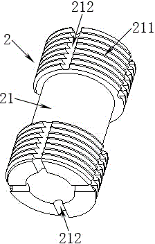
[0044] Such as figure 2 As shown, the shape of the main cavity 2 is a revolving body, and external threads 211 are provided at both ends of the main cavity 2, and cavity air guide grooves 212 are opened on the external threads 211 at both ends. The number of cavity air guide grooves 212 on the external thread 211 at one end of the main cavity 2 is more than one, preferably four in this embodiment. Therefore, a total of 8 cavity air guide grooves 212 are opened at both ends of the main cavity 2 . The cross-section of the cavity air guide groove 212 can be in the shape of semicircle, triangle, square, trapezoid, polygon, star or double wave, and each cavity air guide groove 212 is a long groove.

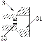
[0045] Such as image 3 As shown, the shape of the radio frequency connector 3 is also a body of revolution, and one end of the radio frequency connector 3 is provided with an internal thread 31 , and a radio frequency air guide groove 32 is opened in the internal thread 31 . The p...

Embodiment 2

[0056] Such as Figure 6 to Figure 9 As shown, in addition to the cavity air guide groove 212, the main cavity 2 is provided with a heat sink 12 in the middle, and the radio frequency connector 3 is provided with a heat sink 12 at one end in addition to the radio frequency air guide groove 32. , the cooling fins 12 are evenly distributed on the main cavity 2 and the radio frequency connector 3 in a radial shape. The main cavity 2, the radio frequency connector 3 and the heat sink 12 are all made of metal, preferably aluminum alloy.

[0057] As in Embodiment 1, the cross section of the air guide groove on the main cavity 2 or the radio frequency connector 3 can be in the shape of a semicircle, triangle, square, trapezoid, polygon, star or double waves, and each guide The air grooves are all elongated groove-like grooves. The position, number, shape and size of the radio frequency air guide grooves 32 correspond to the position, number, shape and size of the cavity air guide g...

Embodiment 3

[0063] Similar to the second embodiment, only the structure of the air guide grooves on the main cavity 2 and the radio frequency connector 3 in the second embodiment is removed. That is to say, the heat dissipation structure in this embodiment is that heat dissipation fins 12 are arranged on the main cavity 2 and the radio frequency connector 3 .

[0064] Regarding the heat dissipation effect of the high-power radio frequency system during operation, the second embodiment is better than the third embodiment, and the third embodiment is better than the first embodiment.

[0065] Since the installation position, function and principle of the synthetic discharge element 5 in the first embodiment, the second embodiment and the third embodiment are the same, the heat prevention of the synthetic discharge element 5 in the three embodiments is in the surge protector 1 The effect of upper aggregation is also consistent.


PUM


Abstract

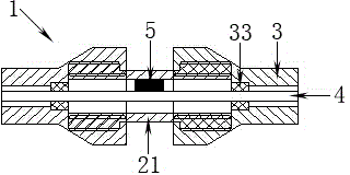
Provided is a high-power radio frequency surge protector which is characterized in that the surge protector is arranged between an emission device and an antenna; two radio frequency connectors are connected to the two ends of a main cavity respectively; the main cavity and the radio frequency connector are provided with a heat-dissipation structure; the main cavity is internally provided with an inner conductor; and one end of a composite discharge element is connected with a cavity housing, and the other end is connected with the inner conductor. The invention relates to the radio frequency surge protector for a high-power emission system. The surge protector is cooled through arranging air grooves in the radio frequency connectors and the main cavity and arranging cooling fins; and through arranging the composite discharge element, capable of automatically returning to a cut-off state after thunder surge discharge, between the inner conductor and the cavity housing, heat generated by continuous current is prevented from being accumulated in the surge protector.

Description

technical field [0001] The invention relates to a radio frequency surge protector for a high-power transmission system, in particular to anti-surge protection for radio frequency signals capable of satisfying 200W to 2000W high-power wireless transmission equipment. Background technique [0002] Wireless communication is to send out high-power wireless signals through the transmitting base station of the operator, and then receive and analyze the signals through the receiver of the terminal, and then present them in people's eyes. Since the 1970s, people have started research on wireless networks. Throughout the 1980s, with the rapid development of Ethernet LAN, the wireless network, which has the advantages of no wiring and strong flexibility, has also won the recognition of specific markets by making up for the shortcomings of "wired". The technology of wireless communication has penetrated into all aspects of people's life and work, including mobile phones and wireless p...

Claims


Application Information

Patent Timeline
IPC IPC(8): H02H9/04H02H9/06H02H3/22
Inventor 倪双兢钟平匡宪伟邓应辉黄仁兴
Owner ZHUZHOU PUTIAN ZHONGPU LIGHTNING PROTECTION TECH
Learn More