Fixed-wing multi-shaft aircraft

A multi-rotor aircraft and fixed-wing technology, applied in the field of aircraft, can solve the problems of slow flight speed of quadcopters, only 25m/s, and long flight time, and achieve good flight efficiency, fast switching, and improved flight speed. Effect

Active Publication Date: 2016-05-04
CHENGDU XUESHANG TECH CO LTD
View PDF5 Cites 65 Cited by
  • Summary
  • Abstract
  • Description
  • Claims
  • Application Information

AI Technical Summary

Problems solved by technology

The four-axis aircraft changes the rotor speed by adjusting the speed of the four motors to achieve a change in lift, thereby controlling the attitude and position of the aircraft. During the adjustment process, the power consumption is relatively large, and high energy consumption directly leads to the problem of short battery life; four-axis The flight speed of the aircraft is slow. At present, the maximum vertical ascent speed of the high-end small and medium-sized quadcopters is generally 9m / s, and the maximum horizontal speed is only 25m / s; etc. are difficult to achieve effectively
Fixed-wing aircraft fly faster in the air, requiring the helmsman to have good responsiveness and strong operating skills. Compared with multi-axis drones, the operation is more complicated
In addition, since the fixed-wing UAV has only one propeller that provides thrust, and the direction is horizontal, there is no external force in the vertical direction of the aircraft to balance the gravity of the aircraft body, and there is no external force to adjust the attitude of the aircraft, so Fixed wings can only use the lift and other forces generated by the wings and tail when flying in the air to maintain balance, but cannot hover in the air
[0005] At present, there is no aircraft that takes into account vertical take-off and landing, hovering in the air, fast flight speed, and long flight time.

Method used


Image

  • Fixed-wing multi-shaft aircraft
  • Fixed-wing multi-shaft aircraft
  • Fixed-wing multi-shaft aircraft

Examples


Embodiment

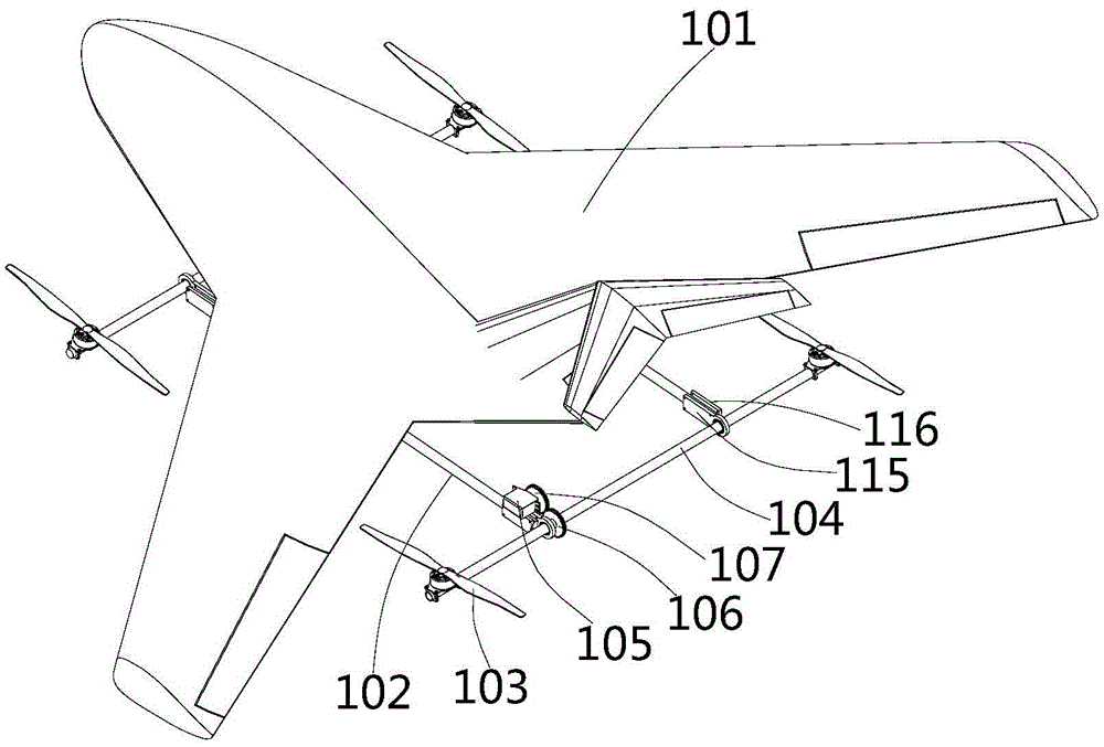
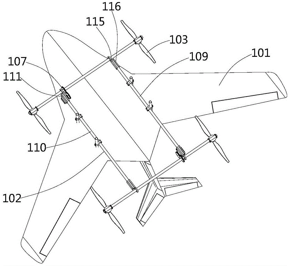
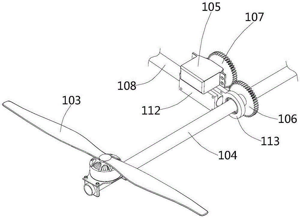
[0052] see figure 1 and figure 2 , the present embodiment provides a fixed-wing multi-axis aircraft, the fixed-wing multi-axis aircraft includes a fixed wing 101 and a multi-axis rotor frame 102 connected to each other, the multi-axis rotor frame 102 is provided with a plurality of rotor mechanisms, and the rotor The mechanism includes a propeller 103 and a rotating shaft 104, the propeller 103 is rotationally connected with the driving device, the driving device is fixedly connected with the rotating shaft 104, and the rotating shaft 104 is connected with the rotation control mechanism.

[0053] There are multiple rotor mechanisms, and the number of propellers 103 is not limited. Each propeller 103 is connected to a driving device, and the driving device is preferably a motor. For example, there are three rotor mechanisms distributed in an isosceles triangle, one of which is located near the head of the fixed wing 101 , and the connecting line of the other two is perpendicu...


PUM


Abstract

The invention provides a fixed-wing multi-shaft aircraft, and belongs to the field of aircrafts. The fixed-wing multi-shaft aircraft comprises a fixed wing and a multi-shaft rotor wing rack which are connected with each other, and the multi-shaft rotor wing rack is provided with multiple rotor wing mechanisms; the rotor wing mechanisms comprise propellers and rotating shafts, the propellers are rotatably connected with drive devices, the drive devices are fixedly connected with the rotating shafts, and the rotating shafts are connected with rotating control mechanisms. The fixed-wing multi-shaft aircraft has the advantages of both a fixed-wing aircraft and a multi-shaft aircraft, can achieve a multi-shaft mode, a fixed-wing mode and a fixed-wing and multi-shaft mixed mode and also has the advantages of achieving vertical taking-off and landing and hovering and being high in flying speed and long in flying time.

Description

technical field [0001] The invention relates to the field of aircraft, in particular to a fixed-wing multi-axis aircraft. Background technique [0002] Currently, there are various types of aircraft, such as quadcopters and fixed-wing UAVs. [0003] The rotors of the quadcopter are symmetrically distributed in the front, rear, left and right directions of the body. The four rotors are at the same height plane, and the structures and radii of the four rotors are the same. The four motors are symmetrically installed on the bracket end of the aircraft, and in the middle of the bracket. The space houses the flight control computer and peripheral equipment. The four-axis aircraft changes the rotor speed by adjusting the speed of the four motors to achieve a change in lift, thereby controlling the attitude and position of the aircraft. During the adjustment process, the power consumption is relatively large, and high energy consumption directly leads to the problem of short batte...

Claims


Application Information

Patent Timeline
Patent Type & Authority Applications(China)
IPC IPC(8): B64C27/22B64C27/28B64C27/26
CPCB64C27/22B64C27/26B64C27/28
Inventor 李吉郑金辉刘良存杜定钟彭智川曾双友袁然
Owner CHENGDU XUESHANG TECH CO LTD
Why Eureka
Try Eureka