Novel sludge storage tank

A mud storage tank and a new type of technology, applied in the field of mud storage tanks, can solve the problems of not being able to work continuously for a long time, affecting the operation of sludge dewatering, and small application range of mud storage tanks, so as to improve the management of sludge dewatering and outbound transportation. , Avoid night transportation, less daily maintenance

Active Publication Date: 2016-05-04
JIANGSU SAIOU ENVIRONMENTAL PROTECTION EQUIP
View PDF7 Cites 0 Cited by
  • Summary
  • Abstract
  • Description
  • Claims
  • Application Information

AI Technical Summary

Problems solved by technology

In the actual use process, most of the equipment has defects such as easy blockage of the sludge outlet and inconvenient management of external transportation, and cannot continue to work for a long time, which will also affect the operation of sludge dewatering
Moreover, the manufacturing cost of these devices is high and the cost performance is low. Due to the above reasons, the general mud storage tank has a small application range.

Method used


Image

  • Novel sludge storage tank
  • Novel sludge storage tank

Examples


Embodiment 1

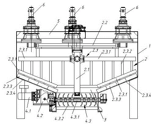
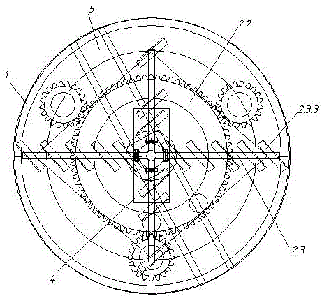
[0010] Embodiment 1: a kind of novel mud storage tank, comprises circular tank body 1, plate type mud pusher 2, mud storage hopper 3, mud storage hopper blanking turning device 4 etc., tank body 1 top has horizontal frame 5, tank body 1 is provided with a plate-type mud pusher 2, which includes a main shaft 2.1 located in the center of the tank body 1, a large transmission gear 2.2 fixedly connected to the main shaft 2.1, and four sets of push arms 2.3. The push arms 2.3 include two angled There are 5 vertical support columns 2.3.2 fixed between the push rod 2.3.1 and the push rod 2.3.1 at 30-60 degrees, and the end of the push rod 2.3.1 is provided with a connecting flange, which is connected to the side wall of the main shaft 2.1 The flange corresponding to the upper part is fixed, and the bottom end of the push rod 2.3.1 is welded with three parallel mud pushing plates 2.3.3. The mud pushing plate 2.3.2 is turned around the longitudinal axis by 25~120 degrees. .3 The bottom...


PUM


Abstract

A novel sludge storage tank comprises a circular tank body, a plate type sludge pushing machine, a sludge storage hopper, a sludge storage hopper falling material overturning device and the like, wherein a transverse rack is arranged at the top end of the tank body; the plate type sludge pushing machine is arranged in the tank body and comprises a spindle, a transmission gear wheel and a pushing arm; the spindle is positioned in the center of the tank body; the transmission gear wheel is fixedly connected with the spindle; the pushing arm comprises two pushing rods and a plurality of vertical supporting columns; an included angle between the two pushing rods is 30-60 degrees; the vertical supporting columns are fixedly connected between the pushing rods; a connecting flange is arranged at the tail end of each pushing rod; the connecting flanges are fixedly connected with flanges which are correspondingly arranged on a side wall of the spindle; a plurality of sludge pushing plates which are parallel to one another are welded to the bottom ends of the pushing rods; the sludge pushing plates overturn at an angle of 25-120 degrees around a longitudinal axis; nitrile rubber plates are arranged on the bottoms of the sludge pushing plates; three gear motors are arranged around an axis of the spindle; a pinion sleeves an output shaft of each gear motor; and all the pinions and the transmission gear wheel on the spindle are in engaged transmission. The novel sludge storage tank is simple in structure and convenient to maintain; sludge can be dehydrated continuously around the clock; and the production efficiency is greatly improved.

Description

technical field [0001] The invention relates to a mud storage and processing device, in particular to a mud storage tank. Background technique [0002] As the country's requirements for environmental protection become more and more stringent, sludge harmless, reduction, and resource-based treatment technologies are becoming the development trend of sludge treatment technology. This involves the storage and transportation of sludge. At present, there are various kinds of mud storage equipment on the market, and the quality is uneven. In the actual use process, most of the equipment has defects such as easy blockage of the sludge outlet and inconvenient management of external transportation, and cannot continue to work for a long time, which will also affect the operation of sludge dewatering. Moreover, the manufacturing cost of these devices is high, and the cost performance is low. Due to the above reasons, the general mud storage tank has a small application range. Cont...

Claims


Application Information

Patent Timeline
Patent Type & Authority Applications(China)
IPC IPC(8): B65D88/54B65D88/68
CPCB65D88/54B65D88/68
Inventor 吴水华吴征王欢曹俊钱俊戴超罗新绿
Owner JIANGSU SAIOU ENVIRONMENTAL PROTECTION EQUIP
Why Eureka
Try Eureka