Pneumatic winding shaft

A technology of rewinding and air inflation, applied in the field of air inflation reel, can solve the problems of inability to unload strip copper foil, inability to meet the requirements of convenient coiling and unloading of strip coiling, etc.

Inactive Publication Date: 2016-05-04
JIANGSU SUNPOWER
View PDF8 Cites 7 Cited by
  • Summary
  • Abstract
  • Description
  • Claims
  • Application Information

AI Technical Summary

Problems solved by technology

[0002] In battery production, tabs are made of copper foil coated material and then cut. Wide copper foil coils need to be cut and rolled into strips. Common shaft rolls cannot roll multiple strips simultaneously. Copper foil unloading, even if the existing rolls with expansion and contraction are used, due to its overall structure, most of them are only suitable for the expansion and contraction of a large coil as a whole, which cannot meet the needs of multiple passes. Convenient coiling and unloading of strip coiling

Method used


Image

  • Pneumatic winding shaft
  • Pneumatic winding shaft
  • Pneumatic winding shaft

Examples


Embodiment 1

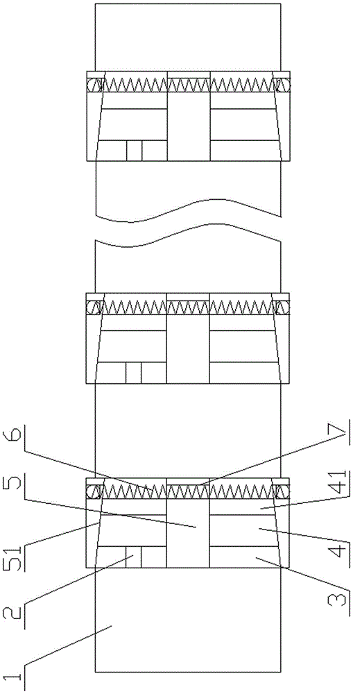
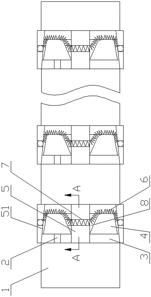
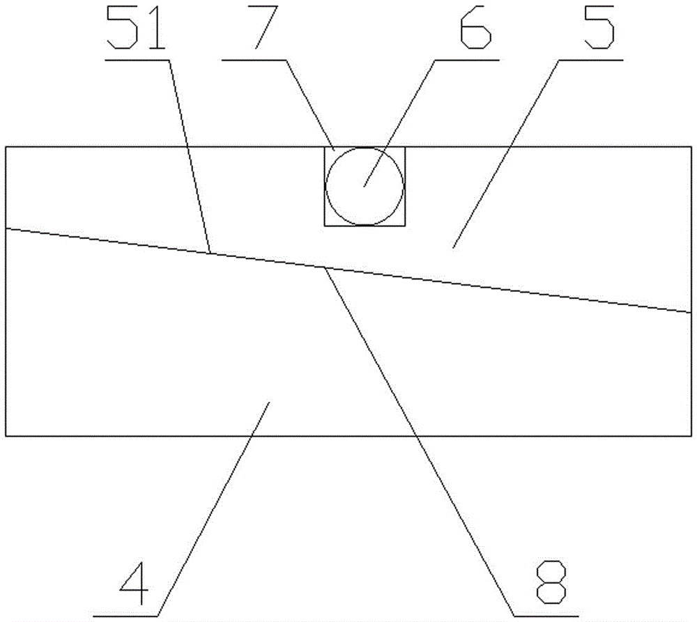
[0016] figure 1 Embodiment 1 shown: an inflatable reel includes a shaft body 1, a plurality of inflatable ring grooves 3 are evenly spaced on the outer peripheral wall of the shaft body 1, and an inflatable device is arranged in the inflatable ring groove 3, and the inflatable device Including an air-expanding push ring 4, a return spring 6 and a plurality of push-out blocks 5, the air-expanding push ring 4 is coaxially installed in the air-expanding ring groove 3 with the shaft body 1 and connected to the air pipe 2 connected in the shaft body to form an air supply The axial displacement state occurs in the air-expanding ring groove under the force, and the outer peripheral wall of one end of the air-expanding push ring 4 is an outer cone 41 structure, and a plurality of push-out blocks 5 are evenly arranged and tightened on the air-expanding push ring 4 through the return spring 6 Above, the inner wall of the ejection block 5 is a structure of the inner tapered surface 51 ma...


PUM


Abstract

The invention relates to a pneumatic winding shaft. The pneumatic winding shaft comprises a shaft body and is characterized in that a plurality of pneumatic ring slots are evenly formed in the external circumferential wall of the shaft wall at intervals, a pneumatic device is arranged in each pneumatic ring slot and comprises a pneumatic push ring, a reset spring and a plurality of push-out blocks, the pneumatic push rings and the shaft body penetrate through the pneumatic ring slots coaxially and are communicated with an air pipe penetrating through the shaft body to be able to move axially in the pneumatic ring slots under air supply stress, the external circumferential wall of one end of each pneumatic push ring is of an external conical structure, the push-out blocks are evenly arranged on each pneumatic push ring trough the corresponding reset spring in a hooping mode, and the inner wall of each push-out block is of an internal conical structure matched with the external conical structure.

Description

technical field [0001] The invention relates to a shaft, in particular to an air-expanding winding shaft. Background technique [0002] In battery production, tabs are made of copper foil coated material and then cut. Wide copper foil coils need to be cut and rolled into strips. Common shaft rolls cannot roll multiple strips simultaneously. Copper foil unloading, even if the existing rolls with expansion and contraction are used, due to their overall structure, most of them are only suitable for the expansion and contraction of a large coil as a whole, which cannot meet the needs of multiple passes. Convenient coiling and unloading for strip coiling. Contents of the invention [0003] Aiming at the deficiencies in the prior art, the present invention provides an air-inflated reel that is simple in structure, compact in use, stable in use, and capable of expanding, uncoiling and shrinking unloading of multi-pass strip coils. [0004] The technical solution of the present ...

Claims


Application Information

Patent Timeline
Patent Type & Authority Applications(China)
IPC IPC(8): B65H75/24B65H75/08
CPCB65H75/243B65H75/08B65H2701/173
Inventor 杨清欣杨春松宋泽斌杨杰
Owner JIANGSU SUNPOWER
Why Eureka
Try Eureka