A screw propulsion external heating type coal dry distillation device

A technology of screw propulsion and screw conveying device, which is applied in the direction of charging device, special dry distillation, coke oven with mechanical device transportation, etc., can solve the problem of low dust content of raw coal gas, avoid complex equipment structure and realize cycle Utilization, the effect of broad market prospects

Active Publication Date: 2017-12-15
王崇峰
View PDF1 Cites 0 Cited by
  • Summary
  • Abstract
  • Description
  • Claims
  • Application Information

AI Technical Summary

Problems solved by technology

[0005] Based on the above-mentioned existing technical problems, the present invention innovatively proposes a screw propulsion material external heating type coal carbonization device. For the first time in the coal carbonization device, the screw propulsion material is used to realize the propulsion of raw coal, and for the first time in the same closed heating The indoor innovative parallel connection of multiple retort chambers effectively solves the problem of raw coal propulsion and heating efficiency in the existing coal retort technology. It has unique advantages such as high value, low dust content, and good economic returns. At the same time, the entire coal dry distillation device is easy to implement and easy to operate. It can be produced in multiple sizes according to the requirements of industrial scale-up. The market has broad prospects

Method used


Image

  • A screw propulsion external heating type coal dry distillation device
  • A screw propulsion external heating type coal dry distillation device
  • A screw propulsion external heating type coal dry distillation device

Examples


Embodiment approach

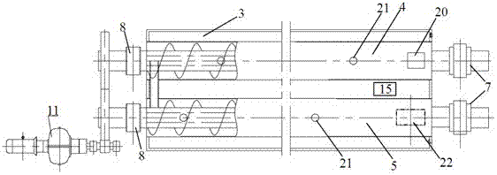
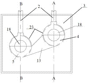
[0048] Attached below Figure 8 to attach Figure 11 The specific composition structure and working process of the second preferred embodiment of the spiral propulsion external heating type coal carbonization device of the present invention are given. as attached Figure 8 to attach Figure 11 As shown, the difference between the second preferred embodiment of the screw propulsion external heating type coal pyrolysis device of the present invention and the above-mentioned first preferred embodiment is only that, in the second preferred embodiment, the front bearing support 7 It is installed inside the heating chamber 3. Specifically, the rear ends of the cylinders of the upper carbonization chamber 4 and the lower carbonization chamber 5 are sealed and fixed on the rear end surface of the heating chamber, and the front ends of the cylinders of the upper carbonization chamber 4 and the lower carbonization chamber 5 are located inside the heating chamber. , and the front end ...


PUM


Abstract

The invention provides a spiral propelling feeding external-heating coal dry distillation device which comprises a heating chamber, dry distillation chambers, spiral conveying devices, a pyrolysis gas collecting chamber, bearing supporting bases, a feeding and discharging mechanism and a drive device. The pyrolysis gas collecting chamber is arranged on the dry distillation chambers and communicated with the dry distillation chambers, heated parts of the dry distillation chambers are located in the heating chamber, the feeding and discharging mechanism is connected with the dry distillation chambers, the spiral conveying devices are arranged in the dry distillation chambers, the ends of the spiral conveying devices are supported by the bearing supporting bases, the drive device is connected to the end of the spiral conveying devices, and a smoke exhaust port is formed in the heating chamber. Raw coal is pushed in a spiral propelling feeding mode in the coal dry distillation device for the first time, the dry distillation chambers are connected in parallel in the same closed heating chamber for dry distillation, the raw coal propelling problem and heating efficiency problem in the existing coal dry distillation technology are solved, and the coal dry distillation device has the unique advantages that coal heating is uniform in the dry distillation process, dry distillation time is short, heating efficiency is high, the tar yield is high, the raw coke oven gas heat value is high, dust content is low, and economic benefits are good.

Description

technical field [0001] The invention relates to coal dry distillation technology, in particular to a screw propulsion material external heating type coal dry distillation device, which belongs to the technical field of pulverized coal medium and low temperature dry distillation. Background technique [0002] Pulverized coal dry distillation technology, also known as coal dry distillation or coal pyrolysis, refers to the process of heating coal under air-isolated conditions to evaporate the tar and gas in the coal to obtain tar, gas, and semi-coke. This technology was first produced in the 19th century and originated in Germany. At the beginning of its invention, it was mainly used to produce coal tar, and also used to produce coke and fuel gas for ironmaking. Due to the high energy conversion rate of this technology, it has always been recognized at home and abroad. It is the third coal conversion technology alongside coal gasification and coal liquefaction, and it is also t...

Claims


Application Information

Patent Timeline
Patent Type & Authority Patents(China)
IPC IPC(8): C10B53/04C10B7/10C10B21/02C10B31/00
CPCC10B7/10C10B21/02C10B31/00C10B53/04
Inventor 王崇峰
Owner 王崇峰
Why Eureka
Try Eureka