Plasma textured cutting tool and its preparation method

A plasma and texturing technology, applied in the direction of ion implantation plating, metal material coating process, coating, etc., can solve the problem of poor ability of micro-texture to capture and store chips, EDM surface ablation, micro-texture Problems such as low dimensional accuracy, to achieve the effect of improving anti-adhesion performance, good anti-adhesion performance, and conducive to storage of chips

Active Publication Date: 2018-03-27
XIAMEN UNIV
View PDF6 Cites 0 Cited by
  • Summary
  • Abstract
  • Description
  • Claims
  • Application Information

AI Technical Summary

Problems solved by technology

[0003] The Chinese invention patent application with the application number 201410823133.9 discloses a new processing method for the micro-texture texture of the pits on the surface of superhard material tools, using an ultrasonic vibration-electric discharge-grinding composite processing platform, and grinding in multiple stages Cutting, electric discharge machining, micro-energy pulse discharge and ultrasonic vibration, the whole set of processing equipment is huge and complex, with many processing steps, and can only obtain micron-level texture on the tool
In addition, the surface ablation of EDM is serious, the processing efficiency is low, and the dimensional accuracy of the micro-texture obtained by processing is not high, the texture cross-section is conical, the space for capturing and storing chips is limited, and the cutting performance of the tool needs to be further improved
[0004] Therefore, the existing micro-textured dry cutting tool preparation methods have technical defects such as difficult processing, uncontrollable micro-texture size and low precision, and poor ability of micro-texture to capture and store chips.

Method used


Image

  • Plasma textured cutting tool and its preparation method
  • Plasma textured cutting tool and its preparation method
  • Plasma textured cutting tool and its preparation method

Examples


Embodiment Construction

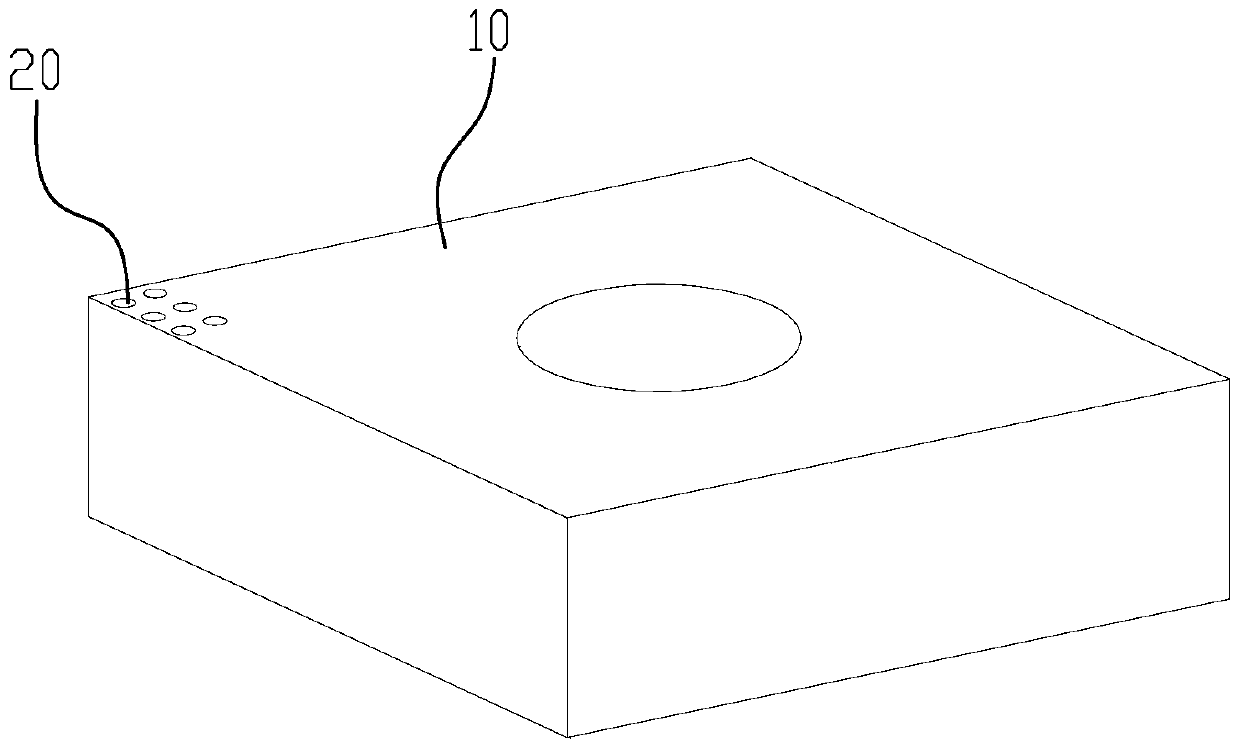
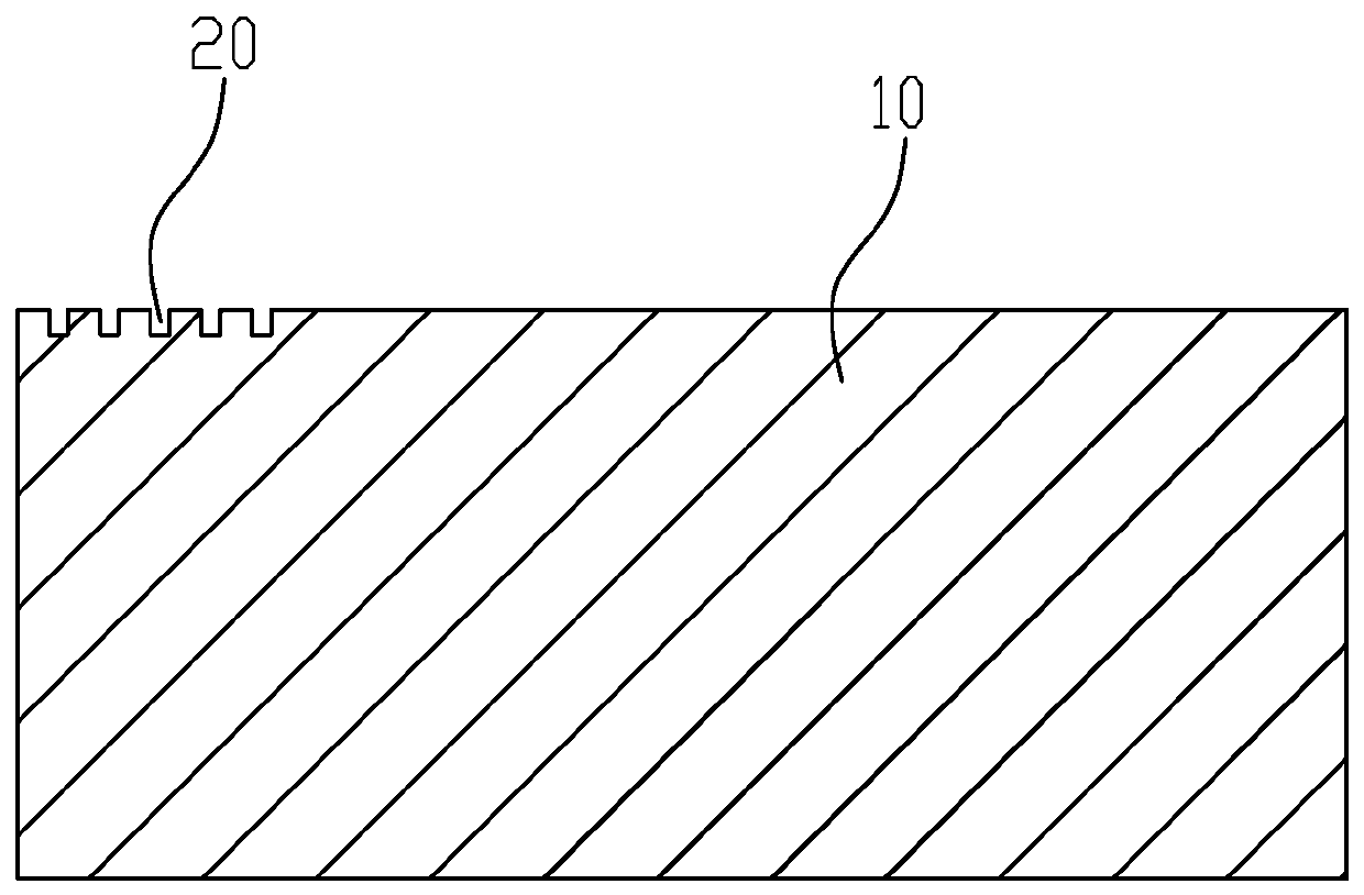
[0033] Please refer to figure 1 with figure 2 , a plasma textured cutting tool 10 of the present invention, the base material of the cutting tool 10 is YG-type cemented carbide (the main component is WC+Co, namely WC / Co cemented carbide). The tool-chip contact area on the rake face of the tool 10 is etched by a plasma etching method to form a nanoscale texture array 20 . The cross-section of the nanoscale textured array is a straight groove. Preferably, the nanoscale textured array 20 has a circular hole diameter=200nm, a circular hole center-to-center distance=300nm, and a circular hole depth=500nm.

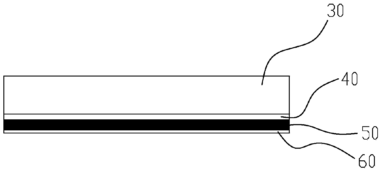
[0034] Please refer to Figure 2 to Figure 9 , the preparation method of above-mentioned cutting tool 10, comprises the steps:

[0035] (1) Prepare the mask plate: as image 3 As shown, the chromium nitride layer 40 is sputtered and deposited on the surface of the glass substrate 30 by sputtering, the chromium film layer 50 is sputtered on the surface of the chromium nitri...


PUM

PropertyMeasurementUnit
thicknessaaaaaaaaaa
thicknessaaaaaaaaaa
diameteraaaaaaaaaa

Abstract

The invention discloses a plasma texturing cutter and a preparing method thereof. The method comprises the steps that firstly, a mask plate is prepared, a chromium nitride layer is sputtered and deposited on the surface of a glass substrate through a sputtering method, a chromium film layer is sputtered on the surface of the chromium nitride layer, a chromium sesquioxide layer is sputtered on the surface of the chromium film layer, and then a nanoscale texture array is machined on the chromium film layer through the electron beam lithography; secondly, pre-treatment of the cutter is carried out; thirdly, photoetching pattern transferring is carried out, a cutter-cuttings contact area of a front cutter face of the cutter is evenly coated with photoresist, exposure is carried out on the photoresist, the photoresist is dissolved through a developing solution, and a nanoscale texture array pattern is formed on the photoresist; and fourthly, plasma etching is carried out, and by means of plasma etching, the nanoscale texture array is formed on the cutter in an etching manner. The cutter-cuttings contact length in the cutting process is reduced through the nanoscale texture array, accordingly, the cutting force and the cutting temperature are reduced, and bonding of cuttings is reduced; and the anti-bonding performance of the cutter is improved, and the service life of the cutter is prolonged.

Description

technical field [0001] The invention relates to a plasma textured cutter and a preparation method thereof. Background technique [0002] In the traditional cutting process, in order to meet the requirements of the surface quality of the workpiece and prolong the service life of the tool, it is usually necessary to use cutting fluid to lubricate and cool the tool continuously. The use of cutting fluid not only requires a higher cost, but also pollutes the environment. In order to reduce the use of cutting fluid, researchers began to devote themselves to the study of dry cutting and the development of new dry cutting tools to meet the performance requirements of dry cutting. The micro-textured tool is a new type of dry cutting tool. By processing the micro-nano structure on the surface of the tool, it can capture and store chips, reduce the cutting force and improve the service life of the tool during cutting. [0003] The Chinese invention patent application with the applic...

Claims


Application Information

Patent Timeline
Patent Type & Authority Patents(China)
IPC IPC(8): C23C14/58C23C14/04C23C14/06
CPCC23C14/042C23C14/0641C23C14/08C23C14/18C23C14/5826C23C14/5873
Inventor 连云崧陈汇丰周伟邓大祥秦利锋
Owner XIAMEN UNIV
Why Eureka
Try Eureka