Joint construction of a prefabricated segmental concrete bridge
A concrete and segmental technology, applied to bridges, bridge parts, bridge materials, etc., can solve the problems of extended construction period, high cost, and long concrete maintenance time, and achieve the effect of improving crack resistance and simple construction operation
- Summary
- Abstract
- Description
- Claims
- Application Information
AI Technical Summary
Problems solved by technology
Method used
Image
Examples
Embodiment 1
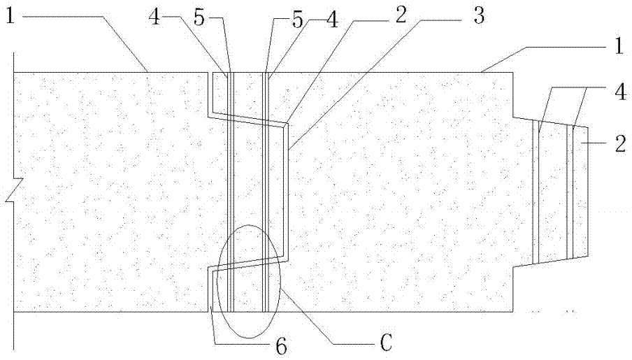
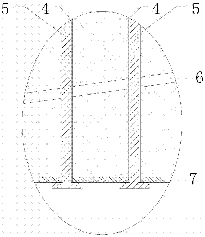
[0023] This example uses figure 1 and figure 2 The segmental seam form shown, where figure 2 is a partial schematic of the bottom of the seam. figure 1 It consists of two adjacent prefabricated segments (1). A bump (2) and a corresponding groove (3) are prefabricated at both ends of the prefabricated segment (1). The front end of the bump (2) is a The vertical surface has a vertical channel (4) on it, and the angle between the upper and lower surfaces of the projection (2) and the horizontal plane is 20 degrees. The joint structure has two rows of tunnels (4) in the longitudinal direction of the bridge, and three rows of tunnels (4) in the transverse bridge direction of the same web. The seam (6) between the vertical bump (2) and the groove (3) is bonded with a modified epoxy resin structural adhesive. After the prefabricated segment (1) is glued, the connecting steel bar (5) made of finished rolled threaded steel bar is penetrated into the tunnel (4), and the connecting...
Embodiment 2
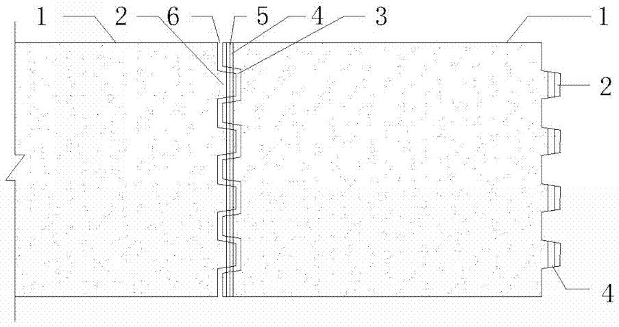
[0025] This embodiment is an amendment to Embodiment 1, using image 3 Segmental seam forms shown. The two ends of the prefabricated segment (1) have a vertical row of four protrusions (2) and corresponding grooves (3), and the protrusions (2) have a row of vertical tunnels (4) in the longitudinal direction of the bridge. After the bonding glue in the joint (6) is cured and reaches the required strength, the connecting steel bar (5) is stretched and fixed, and the modified epoxy resin structural glue is injected into the gap of the channel (4).
Embodiment 3
[0027] This embodiment is an amendment to Embodiment 1, using Figure 4 As shown in the U-shaped connecting steel bar (8), the turning point at the bottom of the U-shaped connecting steel bar (8) is arc-shaped. The two limbs of the U-shaped connecting steel bar (8) respectively penetrate in the two longitudinal tunnels (4) from bottom to top. There is also a corresponding arc knuckle at the place where the lower pre-embedded steel plate (7) is in contact with the arc knuckle of the U-shaped connecting steel bar (8).
PUM
 Abstract
Description
Claims
Application Information
 - R&D
- Intellectual Property
- Life Sciences
- Materials
- Tech Scout
- Unparalleled Data Quality
- Higher Quality Content
- 60% Fewer Hallucinations
Browse by: Latest US Patents, China's latest patents, Technical Efficacy Thesaurus, Application Domain, Technology Topic, Popular Technical Reports.
© 2025 PatSnap. All rights reserved.Legal|Privacy policy|Modern Slavery Act Transparency Statement|Sitemap|About US| Contact US: help@patsnap.com


