Contact Grouting Arrangement Structure and Grouting Method for Steel Substrate of Water Conveyance Tunnel

A technology for water conveyance tunnels and bottom contact, which is applied in infrastructure engineering, hydropower generation, water conservancy engineering, etc., can solve the problems of poor grouting effect, large construction interference, and large number of grouting, so as to improve grouting density and save engineering costs. , the effect of simple construction process

Active Publication Date: 2017-07-28
POWERCHINA HUADONG ENG COPORATION LTD
View PDF5 Cites 0 Cited by
  • Summary
  • Abstract
  • Description
  • Claims
  • Application Information

AI Technical Summary

Problems solved by technology

Since the contact grouting needs to wait 60 days after the concrete pouring is completed, in order to ensure the construction progress, the number of contact grouting pre-embedded pipes drawn out is large and the pipe sections are long, which interferes a lot with the construction and is not economical, and the grouting effect is not good

Method used


Image

  • Contact Grouting Arrangement Structure and Grouting Method for Steel Substrate of Water Conveyance Tunnel
  • Contact Grouting Arrangement Structure and Grouting Method for Steel Substrate of Water Conveyance Tunnel
  • Contact Grouting Arrangement Structure and Grouting Method for Steel Substrate of Water Conveyance Tunnel

Examples


Embodiment 1

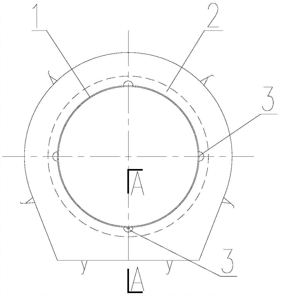
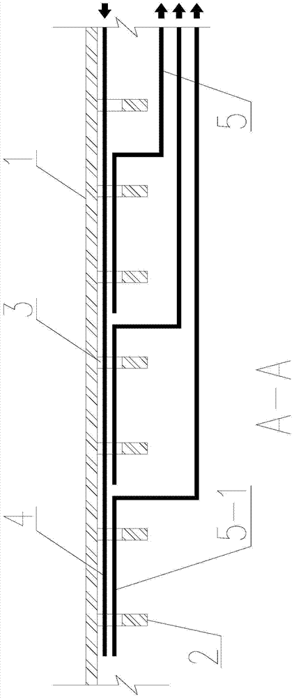
[0028] Such as image 3 As shown, the steel lining 1 is a high-strength steel lining, and the specific implementation steps are as follows:

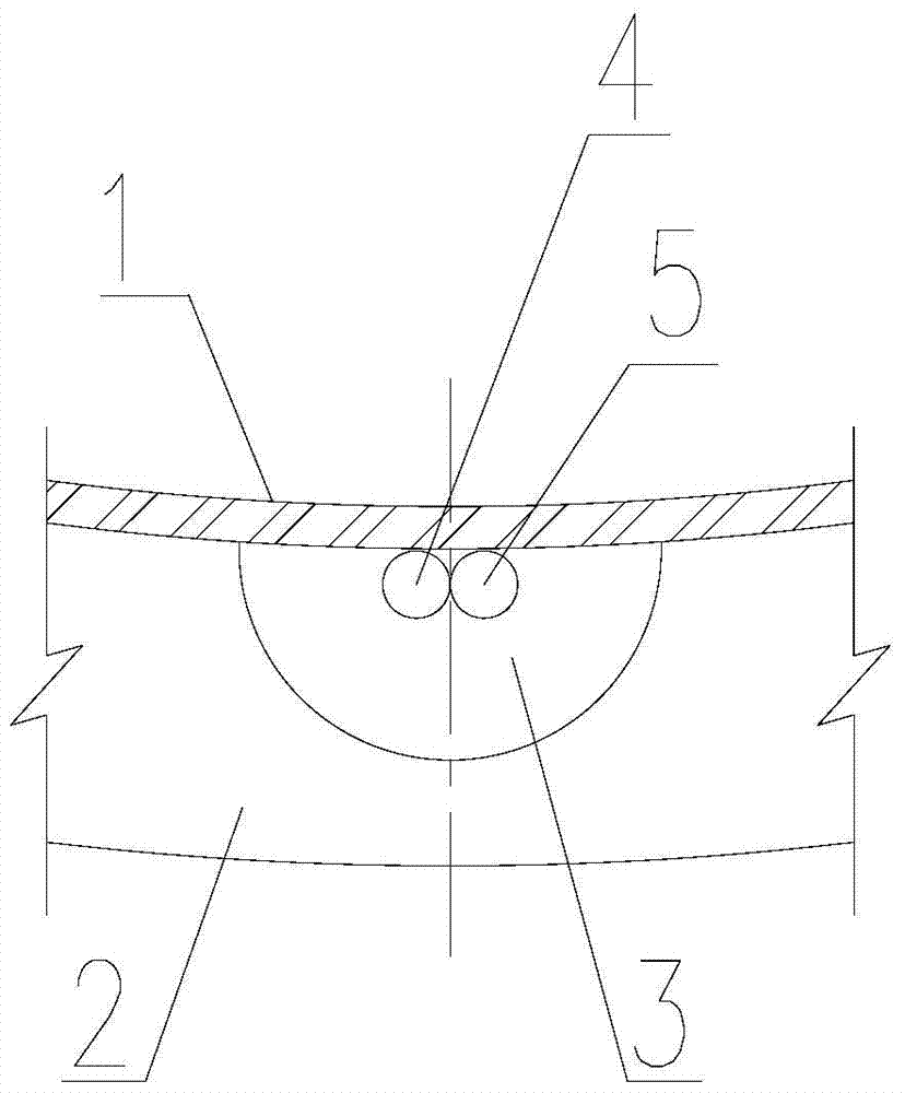
[0029] 1. Embedding of grouting pipe 4: take 30-50m as a grouting section (subject to good control of grouting pressure and grouting quality), and lay grouting in each grouting section close to the outer wall of the steel lining 1 bottom plate. Both the pipe 4 and the slurry inlet pipe pass through the slurry hole 3 at the bottom of the stiffening ring 2; the slurry inlet pipe 4 does not use a conventional seamless steel pipe, but chooses a commercially available one that has been used in some hydropower projects A special grouting pipe (such as FUKO pipe) material that can discharge slurry along the entire pipe section, and can only discharge slurry but not enter slurry;

[0030] 2. Embedding of exhaust and grout return pipe 5: In consideration of ensuring the quality of contact grouting and minimizing the number of buried pipes, an ex...

Embodiment 2

[0033] Such as Figure 4 As shown, the steel lining is a low-alloy steel lining, and the specific implementation steps are as follows:

[0034] 1. For low alloy steel lining (standard tensile strength is less than 540N / mm 2 ), taking 30-50m as a grouting section (subject to the fact that the grouting pressure and grouting quality can be well controlled), since the steel lining 1 can be opened, in each grouting section, every 5-8m on the bottom plate of the steel lining 1 Open a reserved hole 1-1, and set plugs and plugs in the reserved holes (reserved holes 1-1 can refer to the consolidation grouting holes to set up plugs, plugs and other components);

[0035] 2. Embedding of the grout inlet pipe 4: In each grouting section, the grout inlet pipe 4 is laid along the outer wall of the bottom plate of the steel lining 1, and the grout inlet pipe 4 passes through the grout hole 3 at the bottom of the stiffening ring 2;

[0036] 3. Embedding of the exhaust and grout return pipe 5...


PUM


Abstract

The invention relates to a bottom contact grouting arrangement structure of a water conveyance tunnel steel lining and a grouting method thereof, and aims to propose the bottom contact grouting arrangement structure of the water conveyance tunnel steel lining with convenience, safety and high reliability and the grouting method thereof; the number of embedded pipes is low; the engineering cost is saved; the construction process is simple; the construction is not interfered; and the contact grouting effect and quality can be improved. A water conveyance tunnel adopts an embedded steel lining structure; concrete is filled between the outer wall of the steel lining and a surrounding rock; a stiffening ring is arranged on the outer wall of the steel lining by spacing every section; multiple pulp moving holes are formed in the stiffening rings; the tunnel needing the contact grouting uses every 30-50 m as a grouting section; in each grouting section, pulp inlet pipes are tightly laid throughly on the outer wall of a baseplate of the steel lining, and respectively penetrate through the pulp moving holes in the stiffening rings; in each grouting section, an exhaust and pulp return pipe is arranged every 5-8 m; flower pipe sections are set in a 5-8 m range of the end parts of the exhaust and pulp return pipes; and the flower pipe sections all penetrate through the pulp moving holes in the stiffening rings.

Description

technical field [0001] The invention relates to a steel substrate part contact grouting arrangement structure of a water delivery tunnel and a grouting method thereof, which are suitable for water conservancy and hydropower projects. Background technique [0002] Water delivery tunnels of water conservancy and hydropower projects usually adopt buried steel lining structure design in case of special terrain or geological conditions, in order to achieve the purpose of bearing or seepage prevention. In order to realize the combined load bearing of steel lining and surrounding rock, concrete backfill is used between the outer wall of steel lining and surrounding rock to transfer part of the load borne by steel lining to surrounding rock. At the same time, in order to improve the stability of the steel lining structure against external pressure, stiffening rings are usually arranged on the outer wall of the steel lining, with a spacing of generally 1.0 to 1.5m. In order to impro...

Claims


Application Information

Patent Timeline
Patent Type & Authority Patents(China)
IPC IPC(8): E02B9/06E02D15/04
CPCE02B9/06E02D15/04E02D2250/0023E02D2300/0007E02D2300/0029Y02E10/20
Inventor 王东锋姚敏杰陈丽芬蒋磊
Owner POWERCHINA HUADONG ENG COPORATION LTD
Why Eureka
Try Eureka