Automatic sliding door system

A sliding door and automatic technology, applied in door/window accessories, power control mechanism, building, etc., can solve the problems of automatic opening, difficult control, self-heavy, etc., and achieve the effect of fewer parts, stable operation, and simple structure

Active Publication Date: 2017-08-25
NANJING KANGNI MECHANICAL & ELECTRICAL
View PDF7 Cites 4 Cited by
  • Summary
  • Abstract
  • Description
  • Claims
  • Application Information

AI Technical Summary

Problems solved by technology

[0003] Purpose of the invention: The present invention provides an automatic sliding door system to solve the problem in the prior art that the door system using electromagnetic locks will automatically open after power failure, and the structure of the door system using mechanical locks Complicated, self-important, difficult to control, etc.

Method used


Image

  • Automatic sliding door system
  • Automatic sliding door system
  • Automatic sliding door system

Examples


Embodiment Construction

[0041] The present invention will be further described below in conjunction with the accompanying drawings.

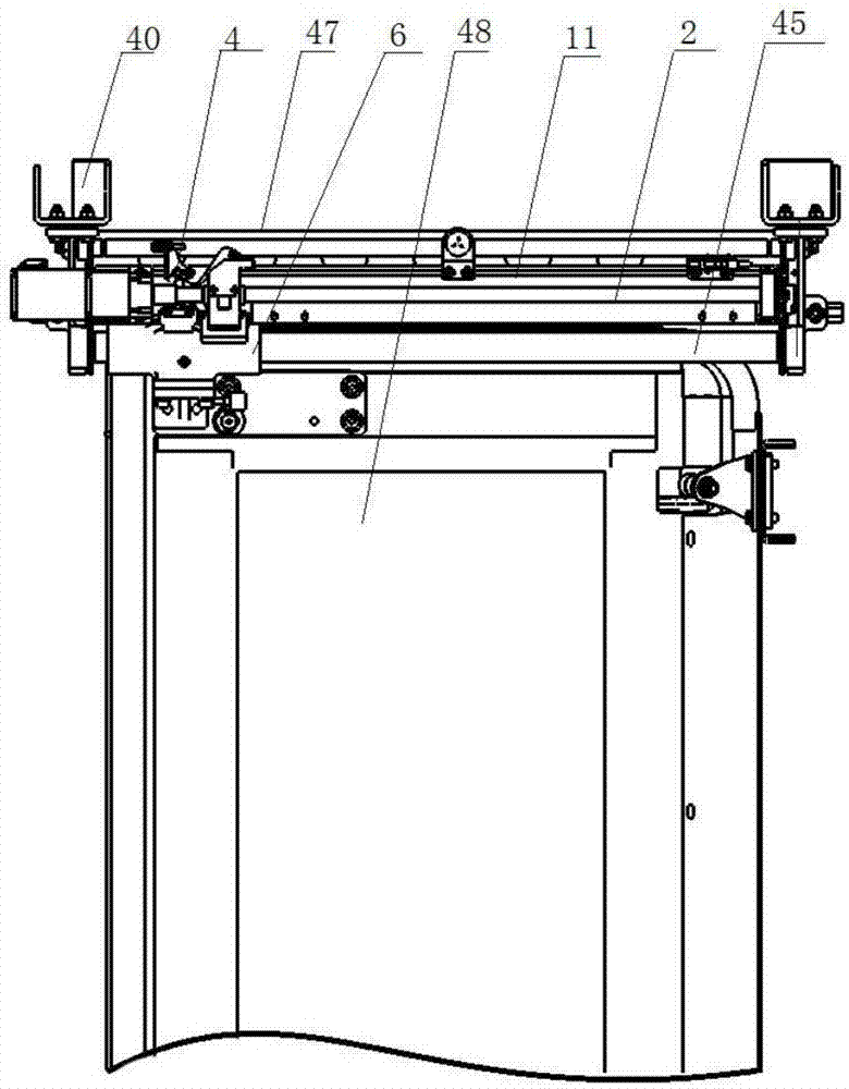
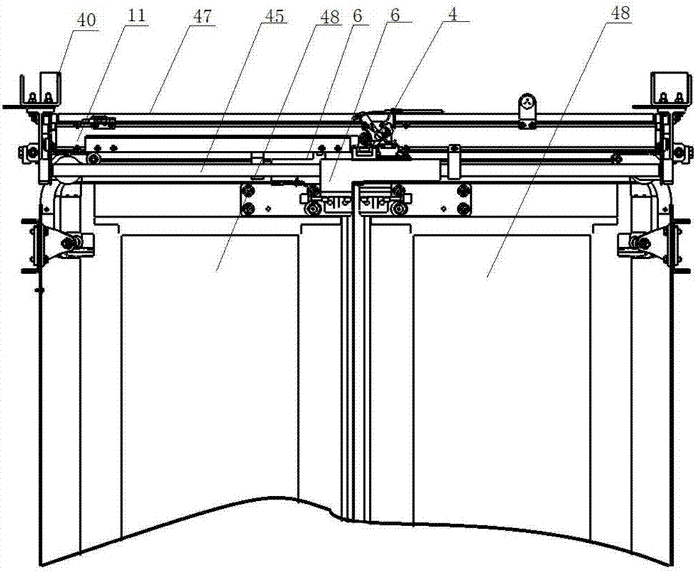
[0042] Such as figure 1 The shown automatic sliding door system includes a crossbeam 11 and a drive mechanism installed on the crossbeam 11 for driving the door to reciprocate. The drive mechanism is connected to the sleeve assembly 6, and the sleeve assembly 6 is connected to the door 48 through the door frame; Hanger 49 is respectively installed at crossbeam 11 two ends, and two long guide pillars 50 are equipped with in parallel between hanger 49, and sleeve assembly 6 is sleeved on the long guide pillar 50, and can reciprocate on long guide pillar 50.

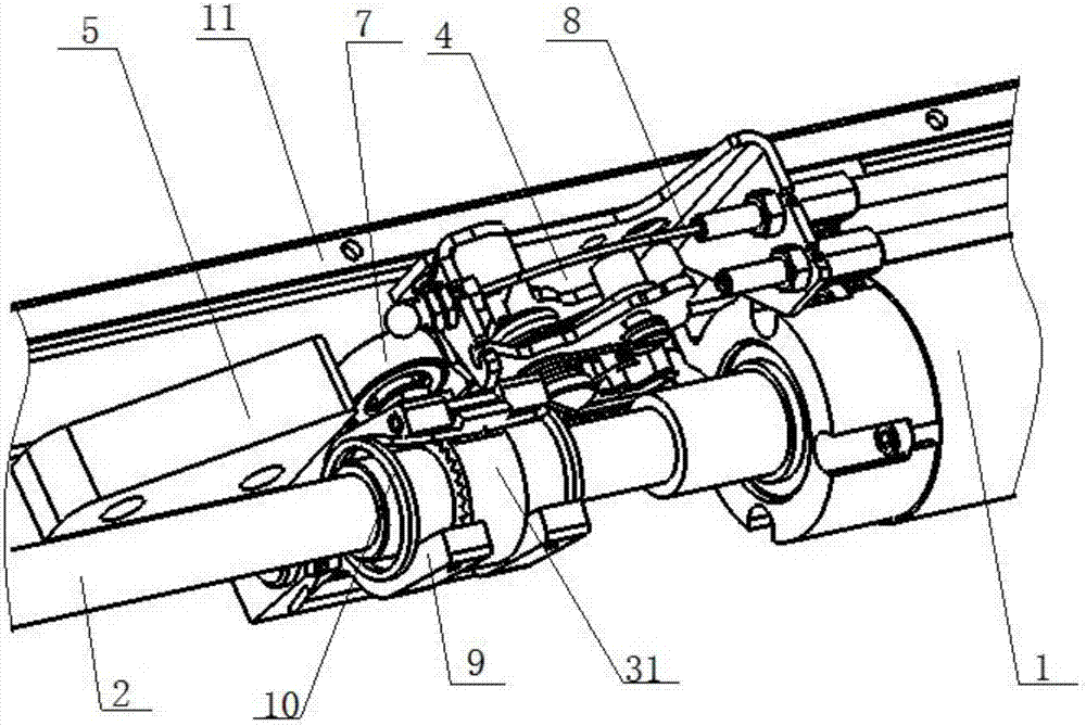
[0043] Such as Figure 3 to Figure 10As shown, the drive mechanism includes a motor 1 fixed on the crossbeam 11, a guide lock block 51 and a limit mechanism 4, the motor 1 is connected to the controller; the shaft of the motor 1 is connected to the screw rod 2, and the screw rod 2 is equipped with nuts in a complet...


PUM


Abstract

The invention discloses an automatic door sliding system. The automatic door sliding system comprises a cross beam, a driving mechanism arranged on the cross beam and a limiting mechanism; the driving mechanism is connected with a sleeve component; a door leaf is connected through a door carrying frame; a guide locking block is arranged on the cross beam; the driving mechanism includes a lead screw driven by a motor and a nut component; the nut component includes a transmission frame, a nut coating the lead screw, and a followup part fixed on the nut; the nut is mounted in the transmission frame; the transmission frame is connected with the sleeve component; the lead screw drives the nut component to perform a reciprocating motion in the axial direction of the lead screw; in forward rotating process of the lead screw, when the followup part is contacted with the guide locking block, the followup part moves to the limiting mechanism under the guidance of the upper surface of the guide locking block and is stopped by the limiting mechanism; the followup part rotates along with the lead screw to enter a space between the side surface of the guide locking block and the limiting mechanism to be locked; and when the lead screw reversely rotates, the followup part reversely rotates along with the lead screw to deviate from the limitation of the guide locking block to be unlocked, and moves in the axial direction of the lead screw.

Description

technical field [0001] The invention relates to the field of automatic control systems, in particular to an automatic sliding door system applied to automatic doors. Background technique [0002] The existing automatic sliding door system generally uses a motor to drive the screw rod, which drives the nut assembly arranged on the screw rod to reciprocate, and then drives the door leaf connected with the nut assembly. Generally speaking, the sliding door system is mostly used in the field of rail transit, bus and other public transportation vehicle doors, and it also has the function of locking and unlocking. Generally used in the sliding door system in the above fields, the nut assembly is locked by the electromagnetic lock, thereby realizing the function of locking the door. In this form of sliding door system, the electromagnetic lock must be energized at any time to ensure the stability of the locked door. If the electromagnetic lock is powered off, there will be a risk ...

Claims


Application Information

Patent Timeline
Patent Type & Authority Patents(China)
IPC IPC(8): E05F15/652
CPCE05Y2900/404E05Y2900/50
Inventor 葛汉青俎文凯戴祖信史旭东贡智兵
Owner NANJING KANGNI MECHANICAL & ELECTRICAL
Why Eureka
Try Eureka