Spiral groove shell used for improving cavitation performance of inducer

A technology of spiral grooves and inducers, which is applied to parts of pumping devices for elastic fluids, jet propulsion devices, liquid fuel engines, etc., to achieve the effects of easy disassembly and improved cavitation performance

Inactive Publication Date: 2016-05-04
BEIHANG UNIV
View PDF3 Cites 5 Cited by
  • Summary
  • Abstract
  • Description
  • Claims
  • Application Information

AI Technical Summary

Problems solved by technology

[0003] Aiming at the problems existing in the existing method for improving the cavitation performance of the inducer, the present invention proposes a spiral groove casing for improving the cavitation performance of the inducer

Method used


Image

  • Spiral groove shell used for improving cavitation performance of inducer
  • Spiral groove shell used for improving cavitation performance of inducer

Examples


Embodiment Construction

[0017] The present invention will be further described in detail below in conjunction with the accompanying drawings.

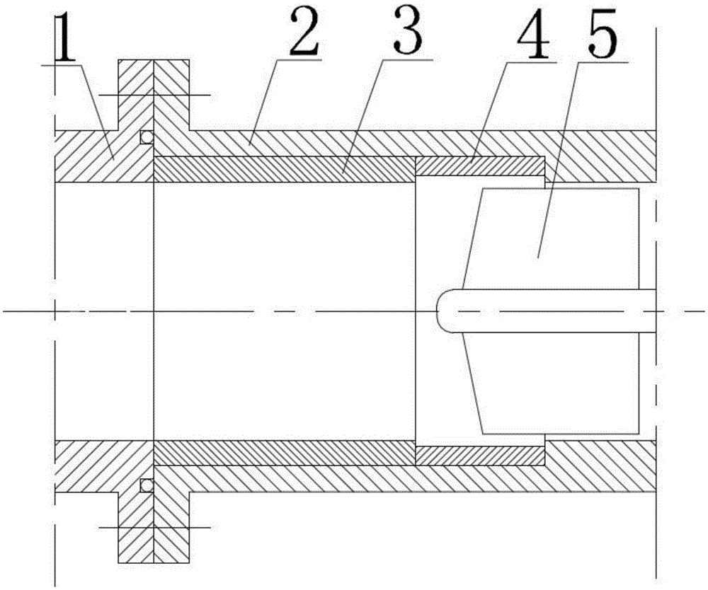
[0018] A spiral groove housing for improving the cavitation performance of the inducer of the present invention, such as figure 1 As shown, it includes upstream pipeline 1 , pump housing 2 , sleeve 3 , spiral groove 4 , and inducer 5 .

[0019] The pump casing 2 is slotted, and the spiral groove 4 is placed in the groove. The spiral groove 4 is located at the entrance of the inducer 5. The position of the spiral groove 4 is fixed by the sleeve 3. The pump casing 2 and the upstream pipeline 1 are connected by bolts. , sealed with a sealing ring.

[0020] As mentioned above, the slotting position of the pump casing 2 is determined according to the installation position of the inducer 5 in the pump casing 2;

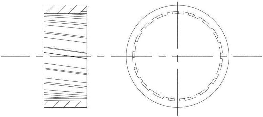
[0021] As mentioned, the depth, width, length, helix angle and number of grooves of the spiral groove 4 are designed according to the size of the induce...


PUM


Abstract

The invention discloses a spiral groove shell used for improving the cavitation performance of an inducer. The spiral groove shell comprises an upstream pipeline, a pump shell, a sleeve, spiral grooves and the inducer. The spiral grooves are installed at an inlet of the inducer, and the turning direction of the spiral grooves is opposite to that of the inducer. The sleeve is used for fixing the positions of the spiral grooves. When the inducer works, backflow of blade tip clearances is enhanced due to the existence of the spiral grooves, and the spiral grooves work on fluid at the same time, so that life of the inducer remains unchanged or is increased slightly.

Description

technical field [0001] The invention belongs to the technical field of liquid rocket engine propulsion, and in particular relates to a spiral groove casing for improving the cavitation performance of an inducer. Background technique [0002] The inducer is an axial flow pump installed in front of the centrifugal pump to improve its cavitation performance. In order to reduce the size of the turbo pump, the inducer is also developing towards miniaturization and high speed, so cavitation phenomenon will inevitably occur inside the inducer. In order to improve the cavitation performance of the inducer, a lot of research has been carried out at home and abroad, and some methods to change the shape of the inducer shell have been proposed, such as opening an annular groove, using a stepped shell, and installing spiral vanes on the shell; or Change the blade shape, such as blade punching, etc. Although these methods can improve the cavitation performance of the inducer to a certai...

Claims


Application Information

Patent Timeline
Patent Type & Authority Applications(China)
IPC IPC(8): F04D29/52F04D29/54F02K9/46
CPCF04D29/528F02K9/46F04D29/548
Inventor 李家文李欣蔡国飙
Owner BEIHANG UNIV
Why Eureka
Try Eureka