Tumbler pull pin

A technology of rotating arms and pin shafts, applied in the direction of bolts, etc., can solve the problems of high manufacturing cost and complex structure, and achieve the effect of low cost, simple structure and convenient adjustment

Active Publication Date: 2016-05-04
NANTONG IRONMASTER SPROTING IND
View PDF6 Cites 4 Cited by
  • Summary
  • Abstract
  • Description
  • Claims
  • Application Information

AI Technical Summary

Problems solved by technology

[0002] At present, the direction of the general pull pin device, the direction of the externally applied adjustment force is parallel to the moving direction of the pull pin shaft, while the direction of the adjustment force is not consistent with the moving direction of the pull pin shaft installed inside the component, the structure is more complicated, and the manufacturing higher cost

Method used


Image

  • Tumbler pull pin
  • Tumbler pull pin

Examples


Embodiment Construction

[0011] In order to deepen the understanding of the present invention, the present invention will be further described below in conjunction with the embodiments and accompanying drawings. The embodiments are only used to explain the present invention and do not constitute a limitation to the protection scope of the present invention.

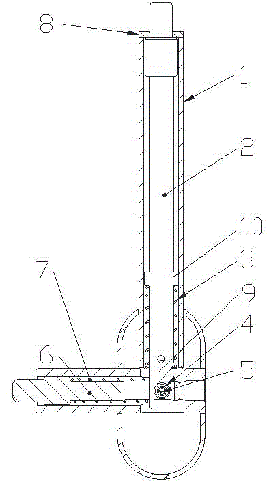
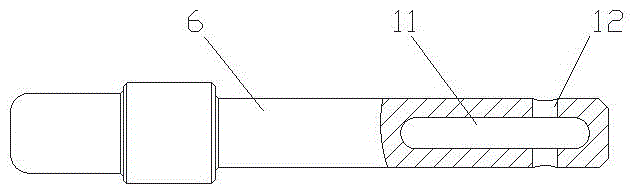
[0012] Such as figure 1 , 2 A pull pin shown in the rotating arm includes an outer sleeve 1, a push handle 2, a first spring 3, a bearing 4, a short shaft 5, a pull pin shaft 6, a second spring 7 and a cover 8, and the push handle 2 is installed on In the longitudinal part of the outer sleeve 1, the first spring 3 is set on the pressing handle 2 and is located between the pressing handle 2 and the longitudinal part of the outer sleeve 1, the pull pin shaft 6 is installed in the transverse part of the outer sleeve 1, and the second spring 7 is set on the pull pin On the shaft 6 and between the draw pin shaft 6 and the lateral part of the outer sl...


PUM


Abstract

The invention discloses a tumbler pull pin which comprises an outer sleeve, a pressing handle, a first spring, a bearing, a short shaft, a pull pin shaft, a second spring and a sealing cover. The pressing handle is installed in a longitudinal part of the outer sleeve, and the first spring is arranged on the pressing handle in a sleeving mode and located between the pressing handle and the longitudinal part of the outer sleeve. The pull pin shaft is installed in a transverse part of the outer sleeve, and the second spring is arranged on the pull pin shaft in a sleeving mode and located between the pull pin shaft and the transverse part of the outer sleeve. The bearing is installed on the pull pin shaft through the short shaft and is in contact with the pressing handle, the sealing cover is installed at the top end of the longitudinal part of the outer sleeve, the pressing handle stretches out of a hole of the sealing cover, an inclined surface is arranged at the end of the pressing handle, a notch is formed in the pull pin shaft, and an installation hole of the short shaft is formed in the pull pin shaft in the direction perpendicular to the notch. The tumbler pull pin has the advantages of being simple in structure, easy to machine and manufacture, low in cost, simple and elegant in appearance and convenient to adjust.

Description

technical field [0001] The invention relates to a pull pin of a rotating arm. Background technique [0002] At present, in the general pull pin device, the direction of the externally applied adjustment force is parallel to the moving direction of the pull pin shaft, while the direction of the adjustment force is not consistent with the moving direction of the pull pin shaft installed inside the component, the structure is more complicated, and the manufacturing higher cost. Contents of the invention [0003] The purpose of the present invention is to overcome the above-mentioned limitations, thereby providing a rotary arm pull pin with simple structure, easy processing and manufacturing, low cost, simple and elegant appearance, and convenient adjustment. [0004] The purpose of the present invention is achieved through the following technical solutions: a rotating arm pull pin, including an outer sleeve, a pressing handle, a first spring, a bearing, a short shaft, a pull...

Claims


Application Information

Patent Timeline
Patent Type & Authority Applications(China)
IPC IPC(8): F16B19/02
CPCF16B19/02
Inventor 李涛王东红查爱萍
Owner NANTONG IRONMASTER SPROTING IND
Why Eureka
Try Eureka