Shift-by-wire actuator and shift-by-wire device

A technology of wire-controlled shifting and actuators, which is applied in the direction of transmission control, components with teeth, belts/chains/gears, etc., which can solve the problems of poor platform versatility and achieve the effect of simple control and simple structure

Active Publication Date: 2020-04-17
GUANGZHOU AUTOMOBILE GROUP CO LTD
View PDF11 Cites 0 Cited by
  • Summary
  • Abstract
  • Description
  • Claims
  • Application Information

AI Technical Summary

Problems solved by technology

[0013] The technical problem to be solved by the present invention is to provide a shift-by-wire actuator for the defects that the transmission needs to be redesigned and the platform has poor versatility when corresponding to different types of automatic transmissions.

Method used


Image

  • Shift-by-wire actuator and shift-by-wire device
  • Shift-by-wire actuator and shift-by-wire device
  • Shift-by-wire actuator and shift-by-wire device

Examples


Embodiment Construction

[0042] In order to make the technical problems, technical solutions and beneficial effects solved by the present invention clearer, the present invention will be further described in detail below in conjunction with the accompanying drawings and embodiments. It should be understood that the specific embodiments described here are only used to explain the present invention, not to limit the present invention.

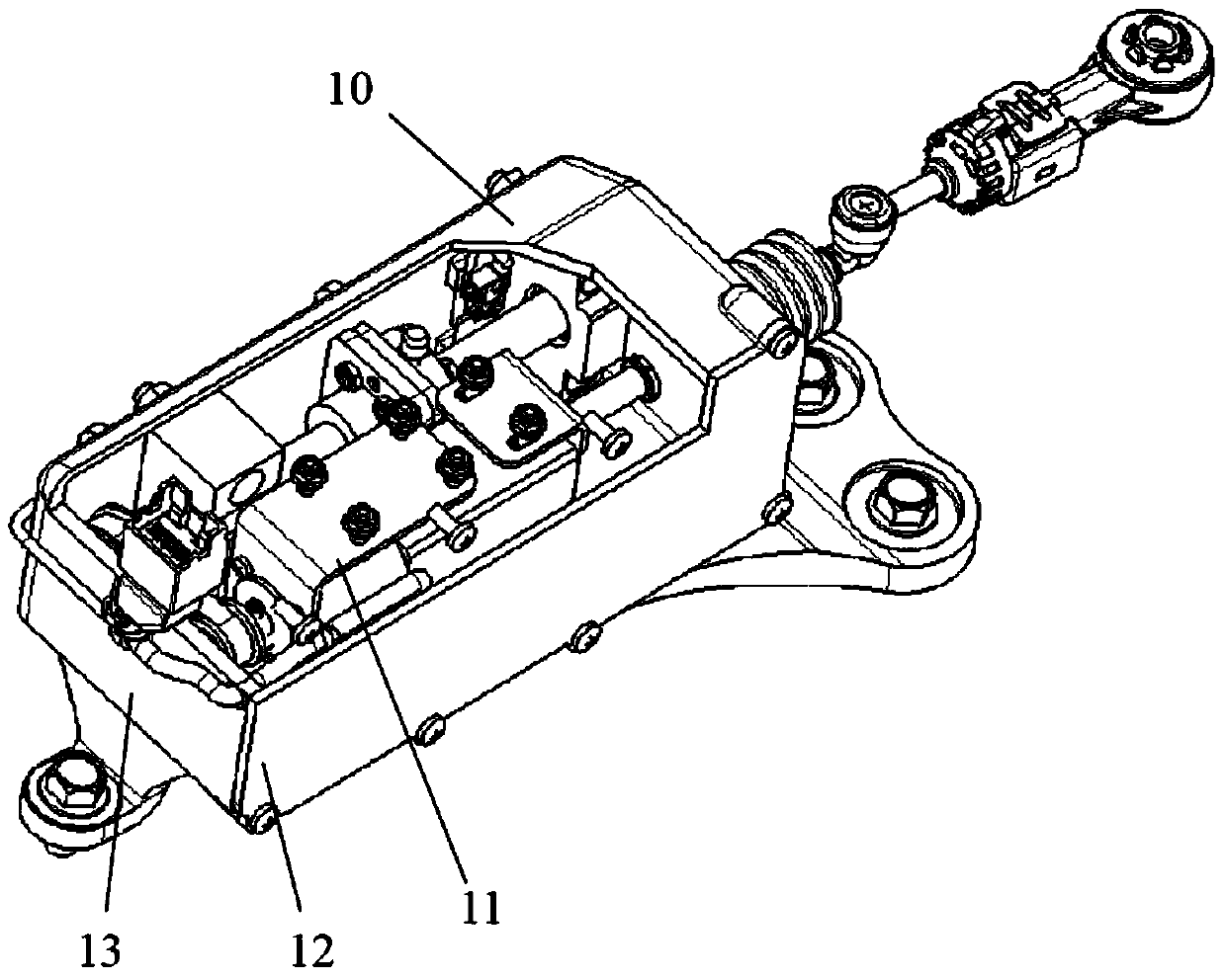
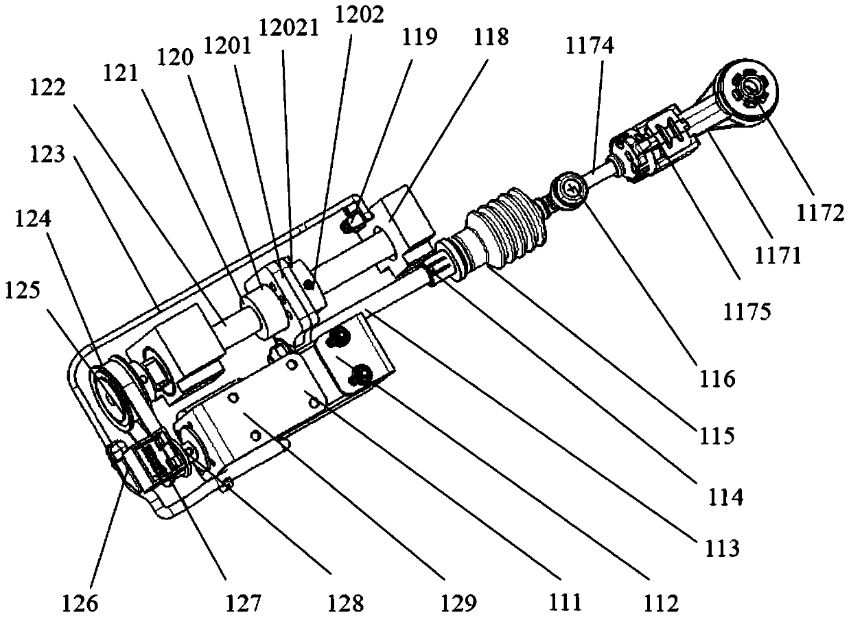
[0043] Such as figure 1 and figure 2 As shown, the shift-by-wire actuator 1 provided by an embodiment of the present invention includes a transmission part 11 and an actuator housing 10, and the actuator housing 10 includes a box body 13 with an opening on one side and a sealed cover for the box body 13 opens the sealing cover 12, thereby forming a sealing space between the box body 13 and the sealing cover 12.

[0044] The transmission part 11 includes a motor 111 , a reducer 128 , a synchronous device, a paired screw rod 122 and a screw nut 121 , a slider 120 , a pu...


PUM


Abstract

The invention provides a shift-by-wire actuator and a shift-by-wire device. The shift-by-wire actuator comprises a motor, an actuator shell, a speed reducer, a pair of a lead screw and a screw nut, a slide block, a push rod and a ball bowl connecting rod; the two ends of the lead screw are rotationally supported on the actuator shell; an input end of the speed reducer is connected with an output shaft of the motor, and an output end is connected with one end of the lead screw; the slide block is fixed on the screw nut; one side surface of the slide block is slidingly contacted with one inner side surface of the actuator shell to limit relative rotation of the screw nut and the lead screw; one end of the push rod is connected to the slide block, and the other end is in ball hinge connection with one end of the ball bowl connecting rod; and the other end of the ball bowl connecting rod is in ball hinge connection with the outer end of a gear shift rocking arm of a vehicle automatic transmission. The shift-by-wire actuator is higher in platform popularity.

Description

technical field [0001] The invention belongs to the technical field of shift control of automatic transmissions of automobiles, in particular to a shift-by-wire actuator and a shift-by-wire device. Background technique [0002] At present, the automatic transmission gear control of mass-produced models basically adopts the method of mechanical cable flexible shaft control. This method requires a mechanical control mechanism (shifter) at one end of the cable, and the cable needs to pass through the central control area, the floor of the body or the firewall and the front cabin, which has certain requirements for the space area. The cable flexible shaft control method requires the shifter to apply a physical stroke and operating force to the cable to drive the cable flexible shaft to move. Transmits force and travel to the control rocker arm on the automatic transmission. The disadvantages of the cable flexible shaft control method mainly include: [0003] (1) The flexible ...

Claims


Application Information

Patent Timeline
Patent Type & Authority Patents(China)
IPC IPC(8): F16H61/32
CPCF16H59/105F16H61/32F16H2061/326
Inventor 刘志刚周厚金谭火南陈振文
Owner GUANGZHOU AUTOMOBILE GROUP CO LTD
Why Eureka
Try Eureka