Direct-heat and constant-temperature circulating heat pump drying machine

A drying machine and constant temperature technology, applied in the direction of drying machine, drying, fluid circulation arrangement, etc., can solve the problems of high mechanical production cost, inconvenience, and unstable temperature

Inactive Publication Date: 2016-05-04
HUBEI KEYANG ENERGY SAVING EQUIP
View PDF8 Cites 3 Cited by
  • Summary
  • Abstract
  • Description
  • Claims
  • Application Information

AI Technical Summary

Problems solved by technology

[0002] The waste heat in the traditional flue-cured room is not recovered, and it is directly discharged to the outside, which wastes a lot of heat energy. Moreover, the heat source of the traditional dryer cannot quickly provide heat with a constant temperature, the heating speed is slow, the temperature is not constant, and the hot air is directly discharged to the outside, resulting in waste heat recovery. low utilization
[0003] For example, the Chinese patent number is "201210202763.5", and the patent name is "High-

Method used


Image

  • Direct-heat and constant-temperature circulating heat pump drying machine

Examples


Embodiment Construction

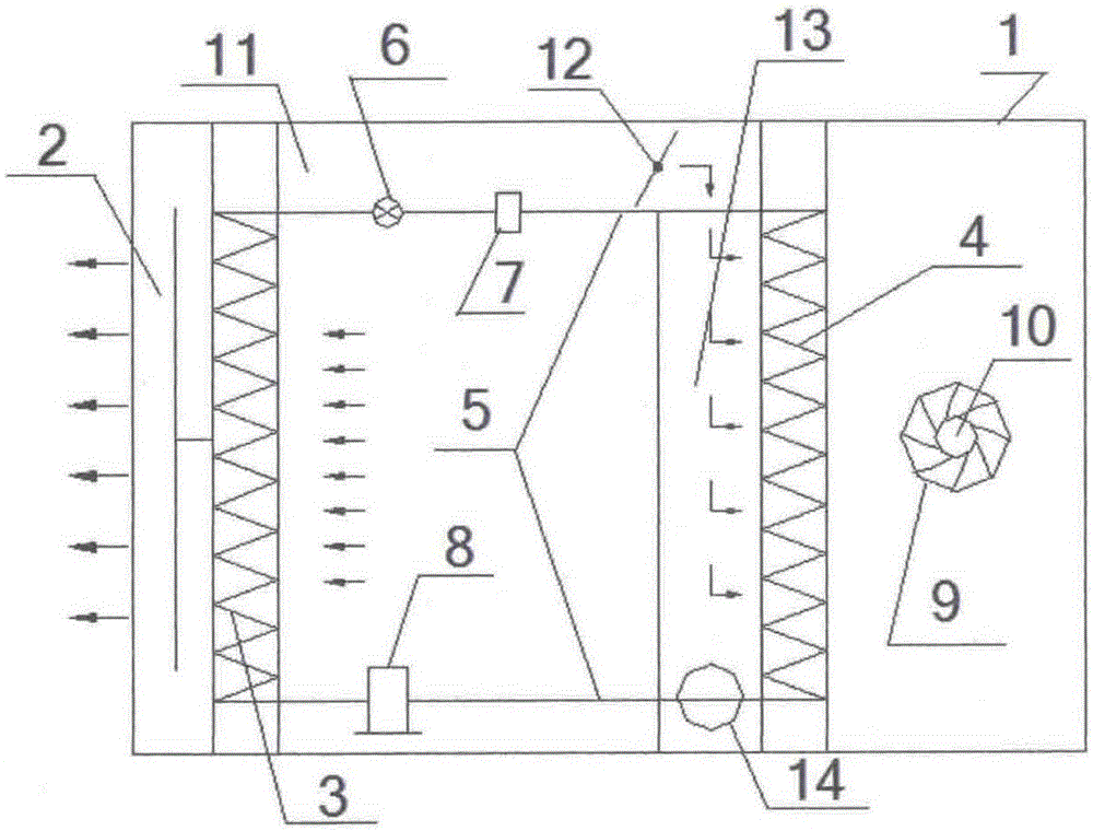
[0009] In this example, refer to figure 1 As shown, a direct heating constant temperature circulation heat pump dryer includes a chassis 1, a fan 2 arranged in the chassis 1, an evaporator 3 arranged on the right side of the fan 2, and a condensing unit arranged on the right side of the evaporator 3 4, and the circulation circuit 5 connecting the evaporator 3 and the condenser 4, and the throttling device 6, the liquid storage tank 7 and the compressor 8 arranged on the circulation circuit 5, and the air outlet arranged on the right side of the condenser 4 9, and the centrifugal fan 10 installed in the air outlet 9.

[0010] Wherein, an air inlet pipe 11 is arranged on the upper surface of the throttling device 6 , and an electric regulating valve 12 is arranged at the end of the air inlet pipe 11 .

[0011] Wherein, the left side of the condenser 4 is provided with an air supply pipe 13, and the connection between the air inlet pipe 11 and the air supply pipe 13 is arranged ...


PUM


Abstract

The invention relates to a direct-heat and constant-temperature circulating heat pump drying machine. The direct-heat and constant-temperature circulating heat pump drying machine comprises a machine case, a draught fan arranged in the machine case, an evaporator arranged on the right side of the draught fan, a condenser arranged on the right side of the evaporator, a circulating loop connected with the evaporator and the condenser, a throttling device, a liquid storage tank, a compressor, an air inlet pipe arranged on the throttling device, an electric adjusting valve arranged at the tail end of the air inlet pipe, an air supply pipe arranged on the left side of the condenser, an air returning port formed in the tail end of the air supply pipe, an air outlet formed in the right side of the condenser, and a centrifugal fan arranged in the air outlet, wherein the throttling device, the liquid storage tank and the compressor are arranged on the circulating loop. According to the direct-heat and constant-temperature circulating heat pump drying machine, the air volume can be adjusted through the electric adjusting valve and the centrifugal fan, and the constant-temperature air discharging is achieved; a circulating air flue is formed through the air outlet and the air returning port, exhausted waste heat can be recycled, and the drying efficiency is high. Heat is absorbed through the evaporator, heating of the evaporator is improved, the effect of energy saving is achieved, the work efficiency ratio of a main machine is increased, meanwhile, the structure is simple, and using is convenient.

Description

technical field [0001] The invention relates to a heat pump dryer, in particular to a direct heating constant temperature circulation heat pump dryer. Background technique [0002] The waste heat in the traditional flue-cured room is not recovered, and it is directly discharged to the outside, which wastes a lot of heat energy. Moreover, the heat source of the traditional dryer cannot quickly provide heat with a constant temperature, the heating speed is slow, the temperature is not constant, and the hot air is directly discharged to the outside, resulting in waste heat recovery. Low utilization. [0003] For example, the Chinese patent number is "201210202763.5", and the patent name is "High-efficiency and energy-saving dense flue-cured tobacco room", which mainly uses a rotary air heat exchanger for heat exchange. The combustion efficiency of the furnace is improved by using part of the flue gas after heat exchange to preheat the air required by the furnace. Although it c...

Claims


Application Information

Patent Timeline
IPC IPC(8): F26B21/00F26B21/12F25B41/04A24B3/10F25B41/20
CPCA24B3/10F26B21/001F26B21/12F26B2200/22F25B41/20
Inventor 文国全蒋家毅
Owner HUBEI KEYANG ENERGY SAVING EQUIP
Why Eureka
Try Eureka