Linear energy gathering smooth blasting device

A smooth blasting and energy-gathering technology, which is applied in the field of rock blasting equipment, can solve problems such as difficult installation, inability to center pre-splitting blasting devices, and large deviation, and achieve the effects of easy installation, convenient transportation, and reduced deviation

Inactive Publication Date: 2016-05-04
CHINA UNIV OF GEOSCIENCES (WUHAN)
View PDF10 Cites 14 Cited by
  • Summary
  • Abstract
  • Description
  • Claims
  • Application Information

AI Technical Summary

Problems solved by technology

Its disadvantages are: ①Because there is no energy-gathering hole on the reducing pipe, a complete pre-splitting surface cannot be formed; ②The pre-splitting blasting device cannot be centered in the hole, and the pre-splitting surface of the actual energy-gathering jet is different from the designed pre-splitting surface. large deviation
As far as the specific structure of its pre-splitting blasting device is concerned, there are the following defects: ① The scheme of connecting the standard section of the energy-collecting tube with the coupling sleeve only limits the radial rotation in the axial direction, and there is no structure to limit its axial movement, so only It can be used for pre-splitting blasting of horizontal blastholes, while in vertical blastholes there is a possibility that the standard section of the energy-concentrating tube and the connecting sleeve will be disconnected; Positioning accuracy is not high

Method used


Image

  • Linear energy gathering smooth blasting device
  • Linear energy gathering smooth blasting device
  • Linear energy gathering smooth blasting device

Examples


Embodiment approach

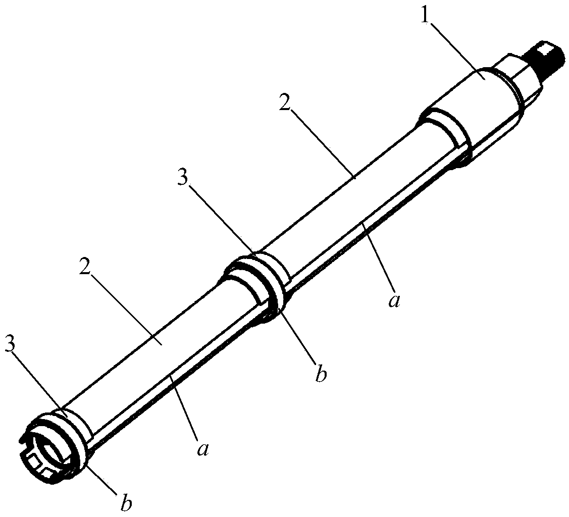
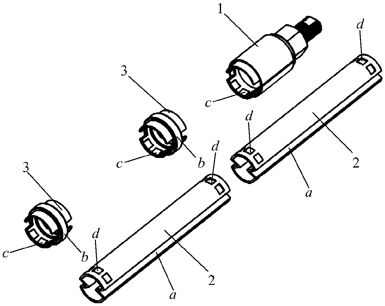
[0043] The orifice fixing device 1 and the energy-gathering standard section 2 of the present invention must meet the requirements of being fixed together, and at the same time meet the requirements of being fixed on the orifice according to the pre-cracking direction;

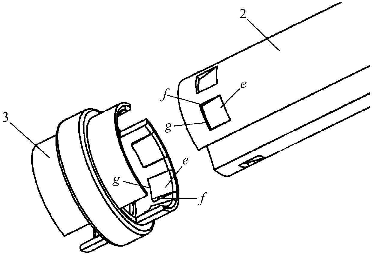
[0044] For the requirement of being fixed together, the present invention has a permanent unilateral buckle or a permanent ring buckle fixed together with the connecting energy-gathering standard section 2 on the connecting rod 11 of the orifice fixing device 1, and it can be made into a protruding surface as required The inner buckle (or outer buckle) or the outer buckle (or inner buckle) of the concave surface, the optimal solution of the present invention is: the inner buckle of the protruding surface;

[0045] For the requirement of being fixed on the orifice according to the pre-splitting direction, the present invention is based on the characteristics of the present invention being fixed in the blast hole...


PUM


Abstract

The invention provides a linear energy gathering smooth blasting device. The device at least comprises an energy gathering standard knot, a centering connecting sleeve and an orifice fixing device opened in the radial direction; and a buckle connecting structure of a permanent single-edge buckle or a permanent annular buckle is used for connecting. The buckle connecting structure realizes fast installation of an energy gathering blasting device; a centering ring structure is adopted to guarantee an energy gathering device to be positioned in the center position of a blast hole so as to reduce the deviation of pre-splitting direction; and the orifice fixing device realizes fast installation of the device after being aligned to the pre-splitting direction. The invention provides the linear energy gathering smooth blasting device with concentrated energy, directional splitting, no coupling charging and convenience for installation for pre-splitting blasting of latent holes and smooth blasting of tunnels. A new product is provided to enterprises for producing blasting devices; a blasting appliance with simplicity, practicability, fast installation and convenience for transportation is provided for construction enterprises performing the pre-splitting blasting engineering operation; and excellent conditions for popularizing and applying the energy gathering smooth blasting technology are satisfied.

Description

technical field [0001] The invention belongs to the technical field of blasting, in particular to an apparatus for blasting rocks. Background technique [0002] The pre-splitting and smooth blasting methods are widely used in open-pit ladder excavation and underground roadway excavation projects. At present, the method of drilling more holes and less charge is widely used to carry out pre-splitting blasting and smooth blasting on rocks. This method has a better blasting effect in igneous rock formations with better rock integrity, but in rocks with poorer integrity. The blasting effect in the sediment layer is poor. For this reason, in recent decades, many scholars have carried out years of research on the pre-splitting blasting of rocks by the linear energy-concentrated blasting method, and obtained a large number of research results, providing a solid theory and practice for the application of the linear energy-concentrated blasting method Base. In recent years, good ac...

Claims


Application Information

Patent Timeline
Patent Type & Authority Applications(China)
IPC IPC(8): F42D1/00F42D1/08F42D3/04
CPCF42D1/00F42D1/08F42D3/04
Inventor 李川
Owner CHINA UNIV OF GEOSCIENCES (WUHAN)
Why Eureka
Try Eureka