
Multifunctional three-dimensional laser scanning target

A three-dimensional laser, multi-functional technology, applied in the field of three-dimensional laser scanner targets, can solve the problems of losing technical advantages, data redundancy, difficulty in obtaining accurate splicing features, etc. simple structure

Inactive Publication Date: 2016-05-04
BEIJING UNIV OF CIVIL ENG & ARCHITECTURE
View PDF8 Cites 16 Cited by
  • Summary
  • Abstract
  • Description
  • Claims
  • Application Information

AI Technical Summary

Problems solved by technology

[0003] 1) Data collection often requires multi-station scanning. Too intensive scanning will greatly increase the time in the field and the amount of data in the office. On the other hand, it is not conducive to data splicing and post-processing, resulting in serious data redundancy
[0004] 2) When the distance between scanning stations is moderate, it is difficult to obtain accurate splicing features, and the accuracy of data splicing cannot be guaranteed. If the method of acquiring targets alone is used, the efficiency of field data collection will be greatly reduced, and technical advantages will be lost
[0005] 3) If the targets currently used for field data acquisition (such as spherical, planar targets, etc.) are not scanned separately, it is generally effective only when the scanning data density is moderate within a range of tens of meters, which cannot meet the requirements of data splicing and global coordinate conversion
[0006] In the actual data collection of the above scenarios, in order to achieve fast data collection, accurate splicing and coordinate conversion, it often takes a lot of time to set up targets in the field

Method used


Image

  • Multifunctional three-dimensional laser scanning target
  • Multifunctional three-dimensional laser scanning target
  • Multifunctional three-dimensional laser scanning target

Examples


Embodiment Construction

[0029] The present invention will be further described in detail below in conjunction with the accompanying drawings, so that those skilled in the art can implement it with reference to the description.

[0030] It should be understood that terms such as "having", "comprising" and "including" as used herein do not entail the presence or addition of one or more other elements or combinations thereof.

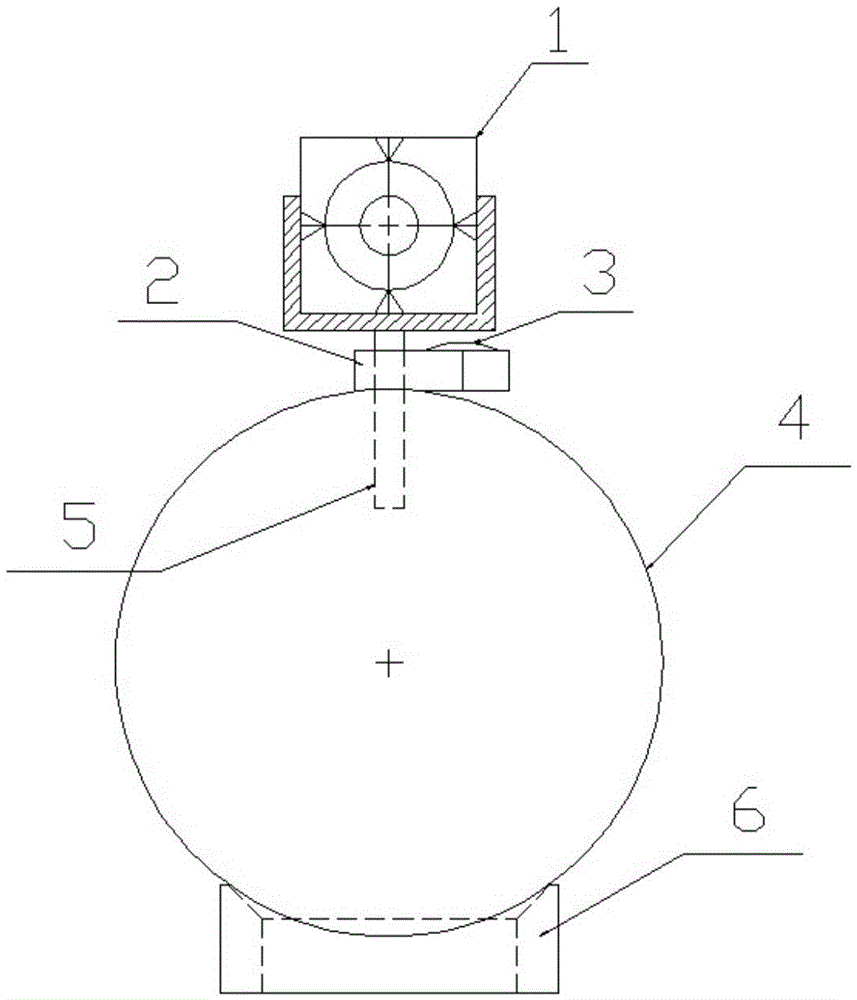
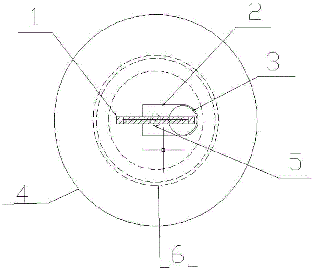
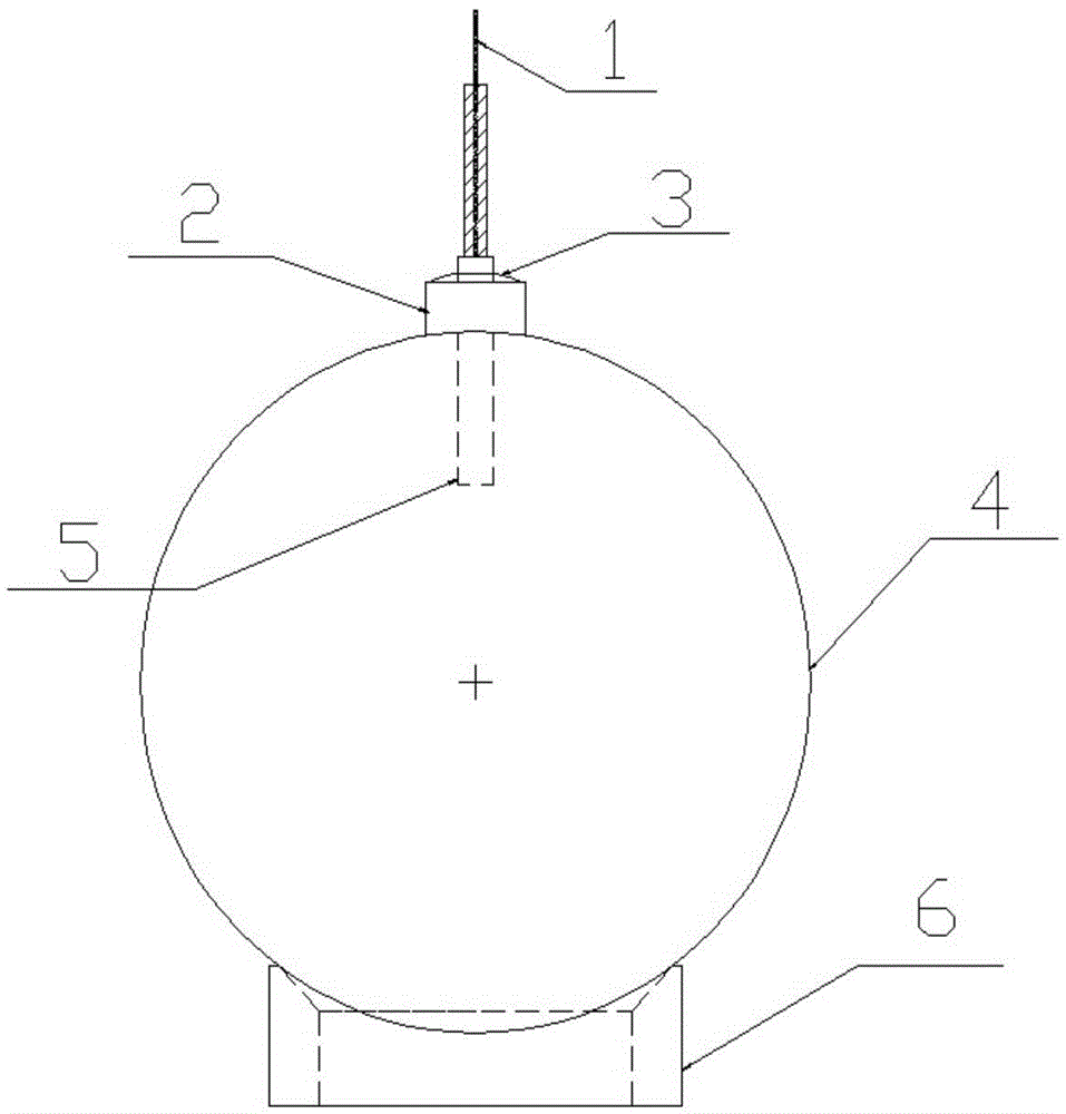
[0031] The invention provides a multifunctional three-dimensional laser scanning target, such as figure 1 , figure 2 , image 3 shown, including:

[0032] The total station reflector 1 is connected to the upper end of the support rod 5 at its lower end to provide a clear target for total station observation. The front of the total station reflector 1 is painted with a target pattern. The center of the reflector is marked with a cross-hair pattern. The reflector 1 of the total station adopts a material with small temperature difference deformation and is light. The reflector 1...


PUM


Abstract

The invention discloses a multifunctional three-dimensional laser scanning target. The multifunctional three-dimensional laser scanning target comprises a total station reflection plate, a horizontal platform and a three-dimensional laser scanning ball, wherein the lower end of the total station reflection plate is connected with the upper end of a supporting rod, the total station reflection plate is used for providing a clear target for total station observation, the horizontal platform is arranged in the middle of the supporting rod, a water level is arranged on the horizontal platform, the upper end of the three-dimensional laser scanning ball is connected with the lower end of the supporting rod, the three-dimensional laser scanning ball is used for a three-dimensional laser scanner to determine a central point coordinate of the three-dimensional laser scanning ball, and a fixed distance exists between the center of the three-dimensional laser scanning ball and the central height of the total station reflection plate. The total station reflection plate, the horizontal platform, the three-dimensional laser scanning ball and a supporting rod axis are located on the same straight line. The multifunctional three-dimensional laser scanning target is simple in structure, reasonable in design, convenient to use and operate and low in cost. In addition, the total station reflection plate and the three-dimensional laser scanning ball are combined, the size of an apparatus is decreased, the laser scanning target is convenient to carry, good in practicability and convenient to popularize and apply, and meanwhile the acquisition efficiency and accuracy of data are improved.

Description

technical field [0001] The invention belongs to the technical field of three-dimensional laser scanner targets, and in particular relates to a multifunctional three-dimensional laser scanning target. Background technique [0002] Ground three-dimensional laser scanning technology is an advanced fully automatic high-precision three-dimensional scanning technology. It obtains fine three-dimensional point cloud data of ground targets through non-contact methods. Its measurement range is currently up to several kilometers, and the absolute measurement accuracy is within a small range. It can reach the submillimeter level (in the range of tens of meters), and is widely used in the fields of ancient buildings and cultural relics protection, digital cities, and building deformation monitoring. For small and medium-sized targets, the scan data is easy to stitch together through overlapping data and features of adjacent sites; however, for large targets, such as relics, terrain data,...

Claims


Application Information

Patent Timeline
Patent Type & Authority Applications(China)
IPC IPC(8): G01C15/02G01B11/24
CPCG01C15/02G01B11/24
Inventor 王国利高威吴贵凯郭明
Owner BEIJING UNIV OF CIVIL ENG & ARCHITECTURE
Learn More