Transformer leakage testing device

A transformer and leak testing technology, which is applied in the direction of measuring the acceleration and deceleration rate of the fluid and using the liquid/vacuum degree for liquid tightness measurement, etc. The effect of reducing connection links, simple connection structure and improving production efficiency

Inactive Publication Date: 2016-05-04
HUBEI HUANDA ELECTRIC CO LTD
View PDF7 Cites 6 Cited by
  • Summary
  • Abstract
  • Description
  • Claims
  • Application Information

AI Technical Summary

Problems solved by technology

The gas injection device simply connected through this kind of gas nozzle is not only inconvenient to use in gas injection and exhaust, but also often has gas leakage, so that it is impossible to judge whether it is the leakage of the transformer box or the gas when the leak test does not meet the conditions. Disqualification caused by air leakage of mouth connection device
As a result, sometimes transformers with good sealing performance will also fail to pass the inspection, resulting in misjudgment of the product qualification rate, which not only affects production efficiency, but also causes waste of manpower and financial resources
In the prior art, the problem of inconvenient gas injection and exhaust is also solved by adding a copper ball valve switch device, but the copper ball valve switch is installed on the gas nozzle, and the gas nozzle is connected to the pressure gauge through a connecting piece. The structure is more complicated, and the airtightness of this connection is not good enough

Method used


Image

  • Transformer leakage testing device

Examples


Embodiment Construction

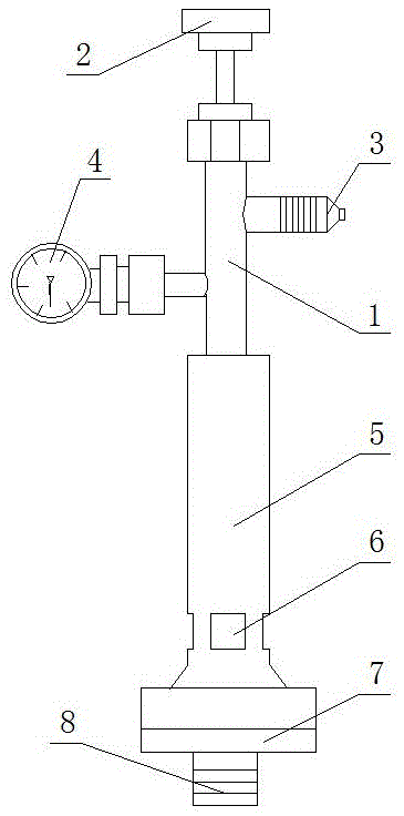
[0012] The transformer leak testing device is composed of a three-way pipeline 1, a connecting joint 8 and a sealing gasket 7. The upper channel of the three-way pipeline 1 is equipped with a rotary valve 2, and the left channel of the three-way pipeline 1 is equipped with a pressure gauge 4, three The threaded gas nozzle 3 connected with the air compressor is made on the right channel of the communication pipeline 1, and the lower end of the three-way pipeline 1 is connected to the pressure test port of the transformer box through the connection joint 5. The connecting joint 5 is connected with the pressure test port of the transformer box through a threaded joint 8, the joint is equipped with a sealing gasket 7, and the lower part of the connecting joint 5 is made with a wrench bayonet 6. (see attached photo).

[0013] The working process of the transformer leak test device is to thread the threaded joint 8 on the lower part of the connecting joint 5 with the pressure test p...


PUM


Abstract

The present invention relates to a transformer leakage testing device, belonging to the field of the transformer production testing technology. The transformer leakage testing device comprises a tee-junction pipeline, an attachment joint and a sealing washer; a rotary valve is arranged at the upper channel of the tee-junction pipeline; a pressure gage is installed at the left channel of the tee-junction pipeline, and a thread air gap connected with an air compressor is arranged at the right channel of the tee-junction pipeline; and the lower end of the tee-junction pipeline is connected with the pressure testing port of a transformer box through the attachment joint. The transformer leakage testing device is simple in connection structure and good in sealing performance, is able to accurately control the testing pressure, and is easy to inject air pressure and exhaust gases by connecting a tee-junction pipeline structure with a rotary valve, a pressure gage and a thread air gap. Besides, the thread air gap and the tee-junction pipeline are integrated to form a one-body structure, so that the connection links are decreased, the airtight of the leakage testing device itself is ensured, the accuracy of the sealing test is greatly improved, and phenomenon is avoided that erroneous judgements are easy to occur in the prior art, therefore the production efficiency is improved.

Description

technical field [0001] The invention relates to a transformer leakage testing device, which belongs to the technical field of transformer production and testing. Background technique [0002] The leakage test of the transformer is related to the sealing performance of the transformer, and the sealing performance of the transformer is one of the important performance indicators of whether the transformer can be safely used in the factory. At present, our commonly used equipment and methods for detecting leaks are to use an air nozzle to fill the transformer box with an air pressure of 50Kpa through the air compressor, and observe the remaining pressure value after 24 hours. The pressure value is not lower than the specified value. If it is 70% of the transformer, we believe that the sealing of the transformer meets the industry regulations; otherwise, it is determined that the sealing of the transformer is unqualified. The gas injection device simply connected through this k...

Claims


Application Information

Patent Timeline
Patent Type & Authority Applications(China)
IPC IPC(8): G01M3/26
CPCG01M3/26
Inventor 张新辉陈彬
Owner HUBEI HUANDA ELECTRIC CO LTD
Why Eureka
Try Eureka