Hydraulic pressure-resistant test method and hydraulic pressure-resistant test device

A test method and test device technology, applied in distribution devices, liquid distribution, conveying or transfer devices, special distribution devices, etc., can solve problems such as high professional skills requirements, artificial control of pressure, waste of time for containers, etc., to reduce labor intensity , slow down the injection flow, reduce the effect of test cost

Inactive Publication Date: 2016-05-04
GUANGZHOU SPECIAL PRESSURE EQUIP INSPECTION & RES INST
View PDF13 Cites 0 Cited by
  • Summary
  • Abstract
  • Description
  • Claims
  • Application Information

AI Technical Summary

Problems solved by technology

[0002] The hydraulic pressure resistance test is a test item involved in the manufacture, inspection and acceptance of the container. The traditional test method is to conduct a hydraulic pressure resistance test on the liquid (water or other specified liquids). Filling the liquid, the traditional method of filling the liquid is to use the same flow rate, manually staring at the pressure gauge of the container to see if it is full, a lot of time is wasted for a large container; after that, slowly increase the design pressure, and rise to the test without leakage Pressure, keep the pressure for no less than 30 minutes, check after enough time to keep the pressure, the pressure should remain unchanged during the inspection
The traditional test method has the following disadvantages: First, it needs to control the pressure manually, which requires high professional skills of the operator; second, it takes a long time to maintain the pressure, which is laborious and inefficient.

Method used


Image

  • Hydraulic pressure-resistant test method and hydraulic pressure-resistant test device
  • Hydraulic pressure-resistant test method and hydraulic pressure-resistant test device

Examples


Embodiment Construction

[0030] In order to make the object, technical solution and advantages of the present invention clearer, the present invention will be further described in detail below in conjunction with the accompanying drawings and specific implementation methods. It should be understood that the specific embodiments described here are only used to explain the present invention, and do not limit the protection scope of the present invention.

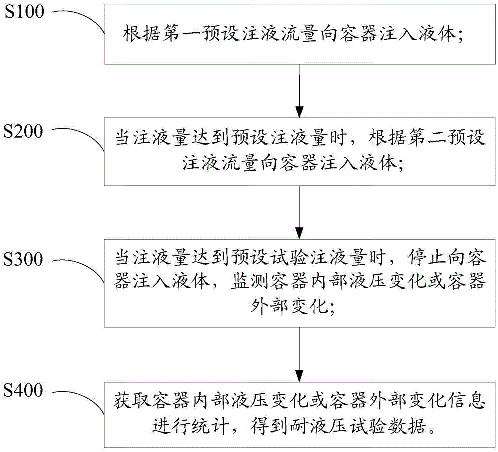
[0031] from figure 1 Shown, a kind of anti-hydraulic test device of the present invention comprises the following steps:

[0032] S100 inject liquid into the container according to the first preset liquid injection flow rate;

[0033] S200, when the liquid injection volume reaches the preset liquid injection volume, inject liquid into the container according to the second preset liquid injection flow rate smaller than the first preset liquid injection flow rate;

[0034] S300 Stop injecting liquid into the container when the liquid injection volume ...


PUM


Abstract

The invention relates to a hydraulic pressure-resistant test method and a hydraulic pressure-resistant test device. The hydraulic pressure-resistant test method comprises the following steps that according to first preset liquid injection flow, injecting liquid into a container; when liquid injection amount reaches preset liquid injection amount, according to second preset liquid injection flow, injecting liquid into the container; when the liquid injection amount reaches preset test liquid injection amount, stopping injecting liquid into the container, and monitoring inner hydraulic change or outer hydraulic change of the container; obtaining inner hydraulic change or outer hydraulic change information of the container for statistics, so as to obtain hydraulic pressure-resistant test data. According to the hydraulic pressure-resistant test method, the liquid injection flow is quickened in an earlier stage of the test, so the liquid injection time is shortened, and the liquid injection flow is delayed in a later stage to ensure the accuracy of the liquid injection amount, so that not only can test efficiency be improved, but also the test accuracy can be improved. The hydraulic pressure-resistant test device is reliable in structure, can intelligently control the liquid injection flow injected into the container, and can improve the test efficiency, and also can improve the test accuracy, reduce labor intensity and reduce the test cost.

Description

technical field [0001] The invention relates to the technical field of hydraulic pressure resistance test, in particular to a hydraulic pressure resistance test method and a device thereof. Background technique [0002] The hydraulic pressure resistance test is a test item involved in the manufacture, inspection and acceptance of the container. The traditional test method is to subject the liquid (water or other specified liquid) to the hydraulic pressure resistance test. Filling the liquid, the traditional method of filling the liquid is to use the same flow rate, manually staring at the pressure gauge of the container to see if it is full, a lot of time is wasted for a large container; after that, slowly increase the design pressure, and rise to the test without leakage The pressure should be kept for no less than 30 minutes, and the inspection should be carried out after a sufficient time for the pressure, and the pressure should remain unchanged during the inspection. T...

Claims


Application Information

Patent Timeline
Patent Type & Authority Applications(China)
IPC IPC(8): G01N3/12B67D7/30
CPCG01N3/12B67D7/30
Inventor 辛明亮邹家华李茂东张术宽王晓林金梅杨波李仕平翟伟
Owner GUANGZHOU SPECIAL PRESSURE EQUIP INSPECTION & RES INST
Why Eureka
Try Eureka