
A Method for Improving the Quality of Ultrasonic Transducer's Delayed Sound Column

An ultrasonic transducer and acoustic column technology, which is applied in the direction of material analysis, instruments, and scientific instruments using sonic/ultrasonic/infrasonic waves, can solve the problems of affecting the detection effect, missed detection and misjudgment, affecting the reception of detection signals, etc. Achieve the effect of improving the detection effect and avoiding missed detection and misjudgment

Active Publication Date: 2021-07-16
AVIC COMPOSITES
View PDF8 Cites 0 Cited by
  • Summary
  • Abstract
  • Description
  • Claims
  • Application Information

AI Technical Summary

Problems solved by technology

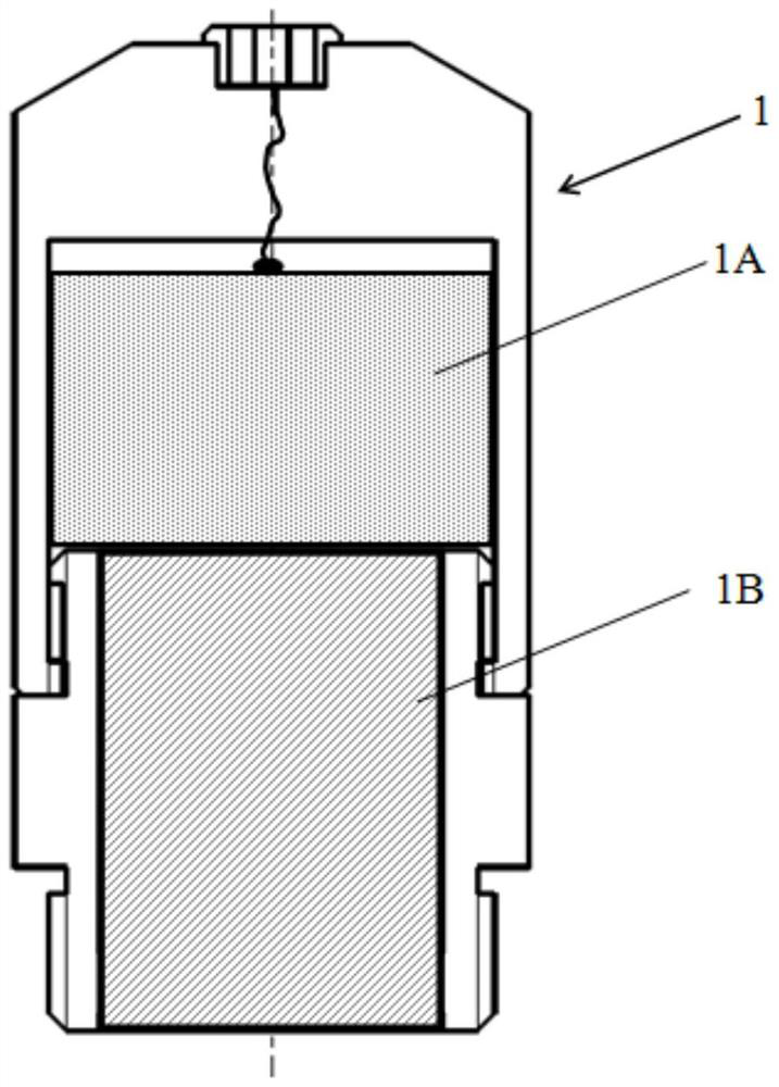
At present, there are two main types of ultrasonic transducers used for manual scanning and detection of composite materials: 1) the solid sound column is used, such as figure 1 As shown, between the piezoelectric unit of the transducer and the surface of the composite material to be detected, the propagation of sound waves is realized through a solid sound-permeable column. The obvious disadvantages are: a) Because the surface of the composite material structure usually shows certain curved features , and the surface is often "convex and convex". Therefore, the actual coupling effect of this sound-transmitting column is very poor, and it is easy to affect the normal transmission / reception of sound waves by the transducer and the additional loss of sound wave signals. Good and stable acoustic coupling is formed on the surface of the material, resulting in missed detection; b) The sound-transmitting column is in hard contact with the surface of the composite material to be detected, which is likely to cause unstable contact of the transducer during manual scanning, affecting the reception of the detection signal, and easily Cause missed detection; c) The solid transparent sound column is easy to wear and deform, resulting in poor contact and coupling of the transducer, which is easy to cause missed detection
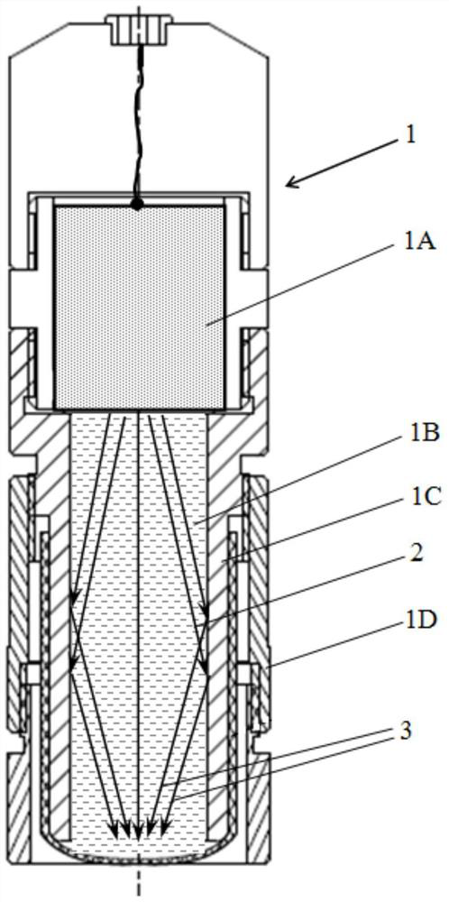
2) To address the above shortcomings, one of the improvement methods is to use the soft membrane 1E coupling, using the liquid in the soft membrane inner cavity 1C as the sound-transmitting column 1B to realize the soft contact coupling between the transducer and the surface of the composite material to be tested. Adjust the contact jacket 1D to achieve the best coupling effect, such as figure 2 As shown, the shortcoming is that when the non-focus transducer is used, due to the radial diffusion characteristics of the emitted sound beam formed from the piezoelectric unit 1A, the sound waves near the center of the piezoelectric unit 1A around the outside will be in the soft membrane The inner wall of the inner cavity 1C forms a diffuse sound wave 2, and after the diffuse sound wave 2 is incident on the inner wall of the pia mater, a reflected sound wave 3 is formed, thereby generating an interference sound wave signal, seriously affecting the detection effect, and easily leading to missed detection and misjudgment

Method used


Image

  • A Method for Improving the Quality of Ultrasonic Transducer's Delayed Sound Column
  • A Method for Improving the Quality of Ultrasonic Transducer's Delayed Sound Column
  • A Method for Improving the Quality of Ultrasonic Transducer's Delayed Sound Column

Examples


Embodiment

[0035] The FJ-1 and FJ-2 liquid time-delayed sound-transmitting column ultrasonic transducers produced by Zhonghang Composite Materials Co., Ltd. are selected, and the sound-absorbing gradient coating is respectively selected from the thickness of the sound-absorbing gradient coating The thickness of layer 4B is 0.6mm, and the thickness of sound-absorbing gradient coating 4C is 1.0mm. 1) When water is selected as the coupling sound column, the brushing sequence is sound-absorbing gradient coating 4A, 4B, 4C, 2) when coupling When silicone oil is selected for the acoustic column, it is painted with sound-absorbing gradient coating 4A. After practical application, a series of practical engineering applications have been carried out on multiple batches and specifications of actual composite material structures ranging from 1000mm to 5000mm in length and 500mm to 3000mm in width, and there is no interference signal of incident sound waves on the outer wall of the liquid delay sound...


PUM

PropertyMeasurementUnit
thicknessaaaaaaaaaa
thicknessaaaaaaaaaa
thicknessaaaaaaaaaa

Abstract

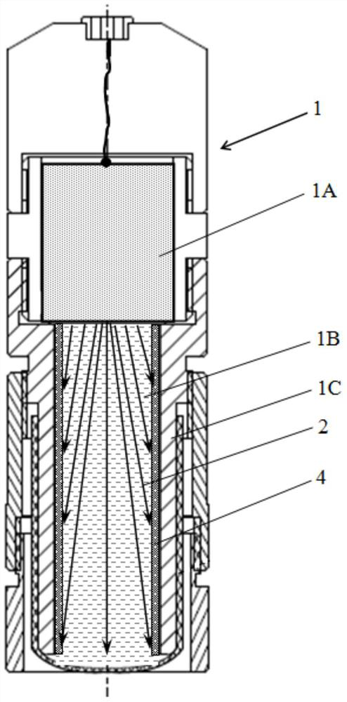
The invention belongs to the composite material structure non-destructive testing technology, and relates to a method for improving the quality of the delay sound column of an ultrasonic transducer used for testing composite materials. Add a sound-absorbing gradient coating to the inner wall of the soft film inner cavity of the liquid sound-permeable column of the ultrasonic transducer, so that the diffuse sound wave formed by the transducer from the piezoelectric unit is absorbed by the sound-absorbing gradient coating and no longer forms Unnecessary interference reflects sound waves. The sound-absorbing gradient coating adopts 3 different gradient distributions. The thickness of the sound-absorbing coating ranges from 0.3mm to 1.0mm. The sound-absorbing gradient coating can form a liquid sound-permeable column with water or oil. 1B is used together. The invention significantly improves the quality of the liquid sound-transmitting column, ensures that the ultrasonic probe forms a stable acoustic coupling with the surface of the composite material to be detected during the scanning process, and at the same time does not cause reflection interference in the inner cavity of the liquid soft membrane, thereby ensuring a stable formation. Ultrasonic detection signals improve the detection effect and defect detection ability, avoiding missed detection and misjudgment.

Description

technical field [0001] The invention belongs to the composite material structure non-destructive testing technology, and relates to a method for improving the quality of the delayed sound column of an ultrasonic transducer used for testing composite materials. Background technique [0002] With the wide application of composite materials in aviation, aerospace, civil aviation, transportation, construction, electric power and other industrial fields, many key engineering structures and complex structures based on structural design and structural manufacturing of composite materials have been continuously installed and applied in engineering. Structural design or load bearing considerations often require 100% scan inspection of composite structures. Ultrasound is currently a major testing method used for non-destructive testing of composite material structures. To achieve ultrasonic testing, it is first necessary to reflect / receive sound waves through ultrasonic transducers. ...

Claims


Application Information

Patent Timeline
Patent Type & Authority Patents(China)
IPC IPC(8): G01N29/24
CPCG01N29/2437
Inventor 刘松平刘菲菲傅天航白金鹏
Owner AVIC COMPOSITES
Learn More