Method of detecting inverter AC and DC-side grounding through single grounding insulation impedance detection network

A grounding insulation and impedance detection technology, applied in the direction of measuring electrical variables, instruments, measuring electricity, etc., can solve problems such as complex system composition and mutual influence

Active Publication Date: 2016-05-04
SINENG ELECTRIC CO LTD
View PDF6 Cites 17 Cited by
  • Summary
  • Abstract
  • Description
  • Claims
  • Application Information

AI Technical Summary

Problems solved by technology

When a ground fault occurs, the DC side judges the positive pole-to-ground voltage V of the square array PV+PE and negative-to-ground voltage V PV-PE The fault is judged by the DC partial voltage situation of the AC side, while the AC s...

Method used


Image

  • Method of detecting inverter AC and DC-side grounding through single grounding insulation impedance detection network
  • Method of detecting inverter AC and DC-side grounding through single grounding insulation impedance detection network
  • Method of detecting inverter AC and DC-side grounding through single grounding insulation impedance detection network

Examples


Embodiment 1

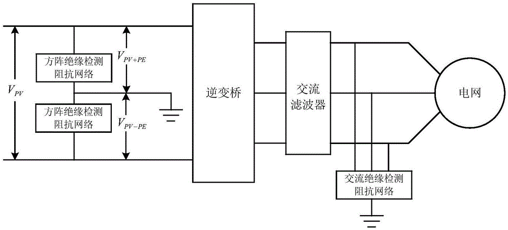
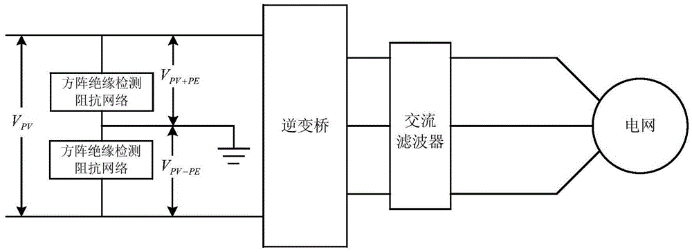
[0025] By analyzing the operating characteristics of the circuit, it is found that when the AC side is grounded, the positive and negative voltage detection waveforms of the DC side will change accordingly, and the AC grounding insulation resistance detection network can be completely removed, thereby simplifying the circuit as follows: figure 2 As shown, by detecting the square array positive pole-to-ground voltage V PV+PE and negative-to-ground voltage V PV-PE The fault information can be obtained by corresponding analysis of the waveform.

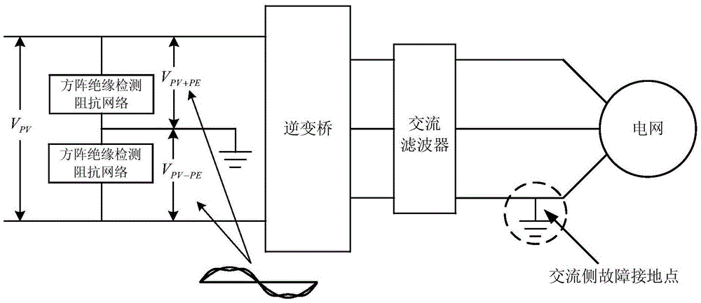
[0026] When a ground fault occurs on any phase of the AC side of the system, if image 3 As shown, the square array positive pole-to-ground voltage V detected on the DC side at this time PV+PE and negative-to-ground voltage V PV-PE The waveform will occur as image 3 The change shown changes from the original straight line to a curve containing output AC side information (the specific waveform is related to the inverter wave).

[0...

Embodiment 2

[0038] Inspired by the above scheme, the DC side grounding can also be detected through the AC side impedance network. The schematic diagram of detecting grounding through the AC side grounding insulation resistance detection network is as follows: Figure 7 As shown, the three phases A, B, and C of the AC side are respectively added to the ground insulation resistance detection network to detect the voltage of A relative to the ground V A-PE , B phase-to-ground voltage V B-PE , C relative to ground voltage V C-PE waveform. Detection principle such as Figure 8 As shown, when the positive / negative pole of the battery board is grounded (in the figure, the negative pole is grounded), the detection waveform on the AC side changes.

[0039] The specific judgment steps are as follows. Figures 9 to 11 The values ​​on the middle ordinate depend on the actual voltage.

[0040] 1. Under normal circumstances, V A-PE , V B-PE , V C-PE waveform like Figure 9 As shown, the dete...


PUM


Abstract

The invention provides a method of detecting inverter AC and DC-side grounding through a single grounding insulation impedance detection network. The method comprises steps: a grounding insulation impedance detection network is only added to the input side of a solar array, and waveforms of the DC-side array positive electrode grounding voltage VPV+PE and the negative electrode grounding voltage VPV-PE are detected; or, the grounding insulation impedance detection network is only added to the AC output side to detect waveforms of AC-side three-phase grounding voltage VA-PE, VB-PE and VC-PE; and as for the former, AC components in the waveforms are extracted to judge the AC-side grounding condition, and as for the latter, DC components in the waveforms are extracted to judge the DC-side grounding condition. The method has the advantages that an AC/DC-side grounding detection method is brought forward, on the basis of adding the grounding insulation impedance detection network only at the input side/output side, the grounding fault of the AC output side/DC side can be judged, the detection circuit is saved, and the system composition is simplified.

Description

technical field [0001] The invention relates to a method for detecting the grounding of the AC and DC sides of an inverter through a single grounding insulation impedance detection network, which is used for detecting the grounding fault of a solar power generation system. Background technique [0002] In the field of solar power generation, ground faults exist as a relatively common fault. In order to ensure the safety of personnel and the reliable operation of equipment, ground fault detection becomes very important. [0003] From the point of view of grounding, it can be roughly divided into two categories: solar array grounding and AC side output grounding. In order to accurately detect grounding, the traditional method is to add grounding to the input side of the solar array and the output side of the inverter. The insulation impedance detection network can judge the grounding condition of the inverter equipment or the solar array by detecting the voltage change of the ...

Claims


Application Information

Patent Timeline
IPC IPC(8): G01R31/00G01R31/02
CPCG01R31/00G01R31/50
Inventor 叶青俞健葛鹏霄
Owner SINENG ELECTRIC CO LTD
Why Eureka
Try Eureka