A layered forced-spreading core melt trap

A core melt and trap technology, which is applied in the field of core melt traps, can solve problems such as the full expansion of the melt without considering the means of layered forced spreading, so as to avoid failure of protective barriers, reliable cooling methods, total reduction effect

Active Publication Date: 2020-03-24
CHINA NUCLEAR POWER ENG CO LTD
View PDF28 Cites 0 Cited by
  • Summary
  • Abstract
  • Description
  • Claims
  • Application Information

AI Technical Summary

Problems solved by technology

[0004] All of the above patents related to the core catcher do not consider the use of layered forced spreading to achieve full expansion of the melt, thereby maximizing the heat transfer of the melt

Method used


Image

  • A layered forced-spreading core melt trap
  • A layered forced-spreading core melt trap
  • A layered forced-spreading core melt trap

Examples


Embodiment 1

[0041] In embodiment one:

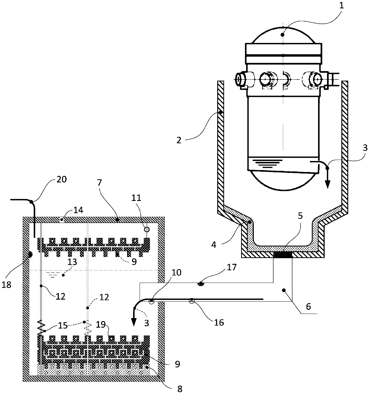
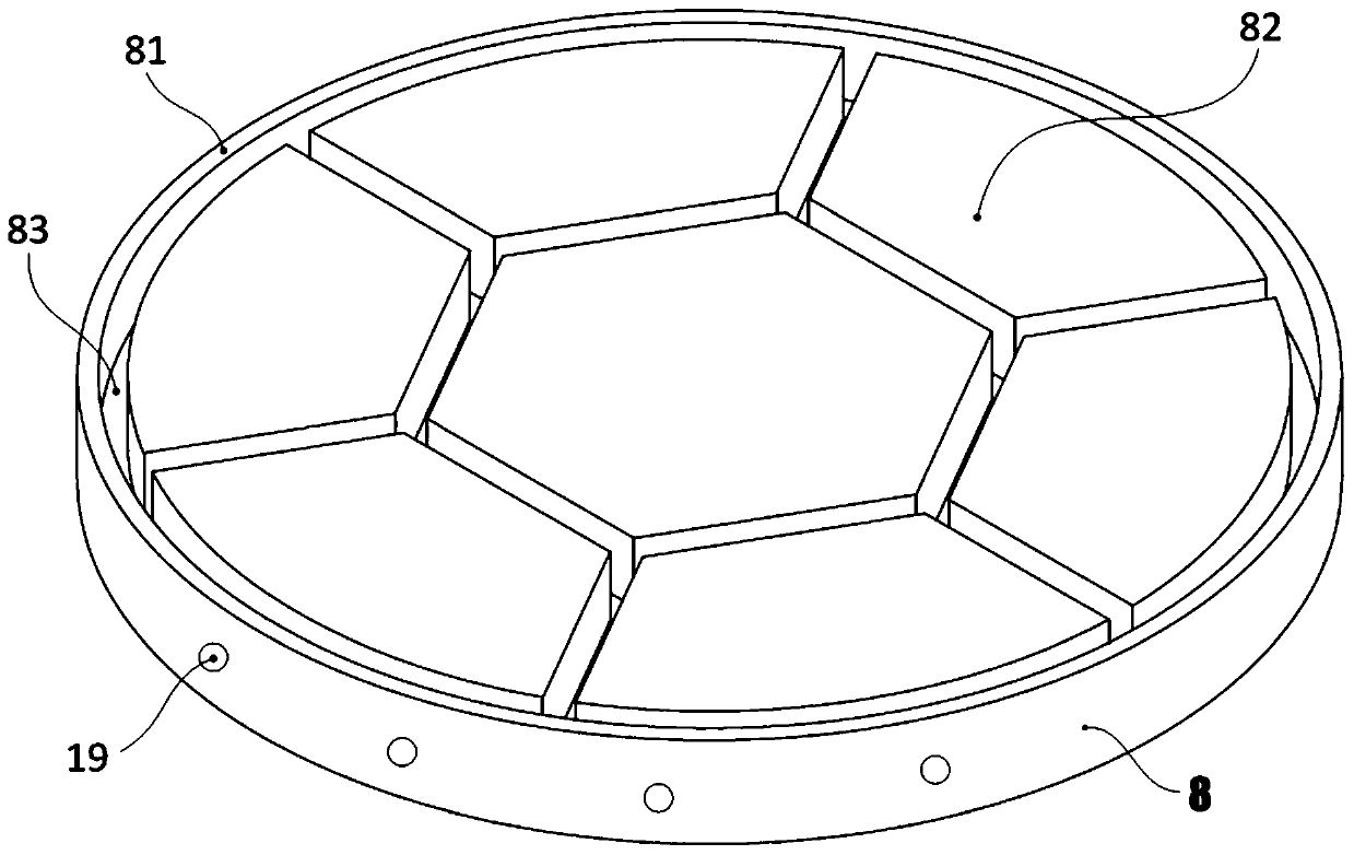
[0042] Trap bottom plate 8 (see figure 2 ) The outer edge of the catcher bottom plate is provided with a contour convex edge 81 of the catcher bottom plate, and the inner plate surface is provided with several polygonal catcher bottom plate protrusions 82 and catcher bottom plate depressions 83;

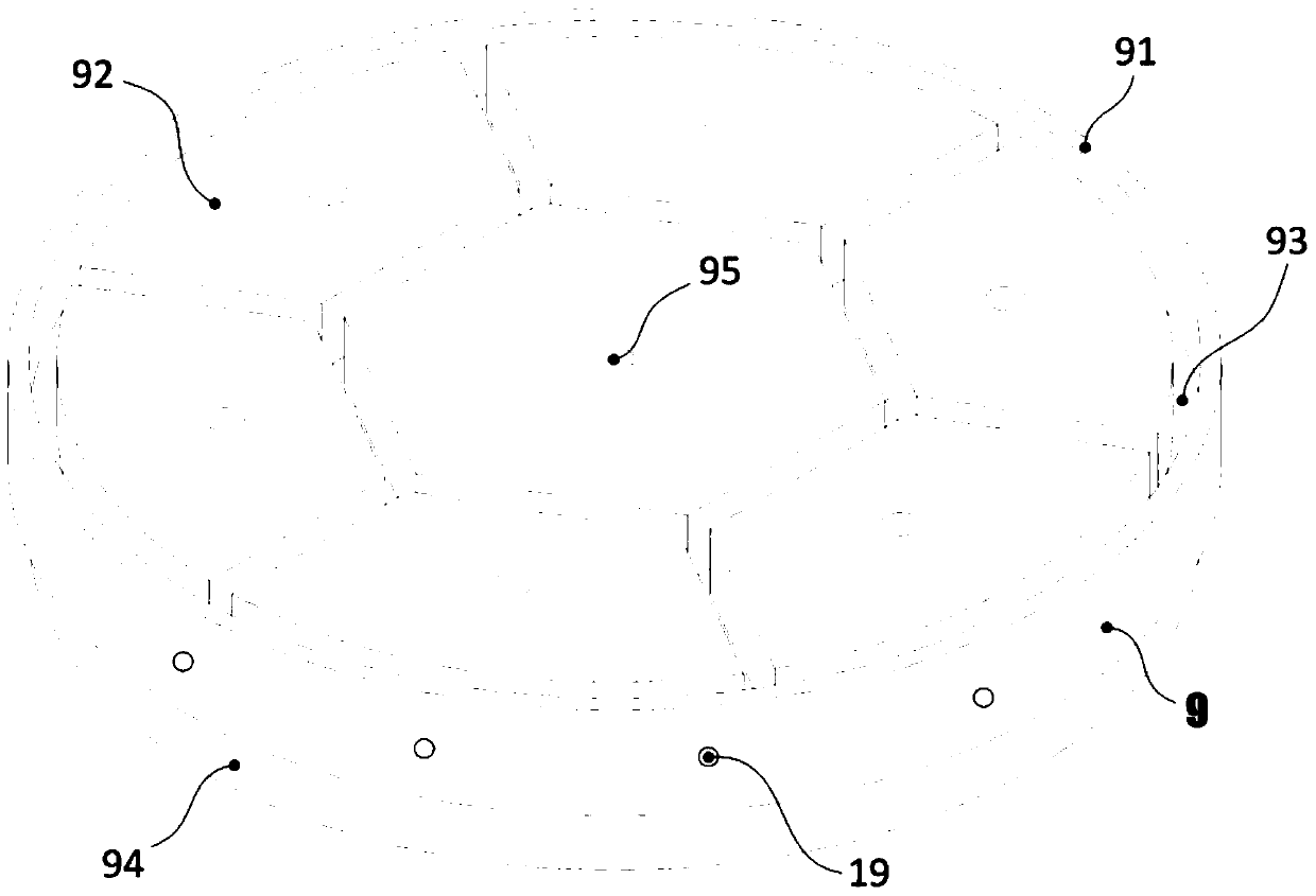
[0043] Such as image 3 , Figure 5 As shown, the outer edge of the upper surface of the catcher cover 9 is provided with a convex edge 91 (protruding upwards) on the catcher cover outline, and a number of catcher cover protrusions 92 are arranged on the inner surface of the upper surface. And catcher cover plate depression 93, catcher cover plate through hole 95 is arranged on catcher cover plate protrusion 92; Figure 4 As shown, the peripheral edge of the lower surface of the catcher cover plate 9 is provided with a convex edge 94 (protruding downward) of the catcher cover plate outline, and several downwardly protruding catches are arranged on the ...

Embodiment 2

[0046] In the second embodiment:

[0047] Such as Figure 7 As shown, the outer edge of the catcher bottom plate 8 is provided with a catcher bottom plate contour convex edge 81, and the inner plate surface is provided with several continuous wave-shaped catcher bottom plate protrusions 82 (wave crests) and catcher bottom plate depressions. 83 (trough);

[0048] Such as Figure 8 , Figure 9 As shown, the outer edge of the upper surface of the catcher cover 9 is provided with a convex edge 91 (protruding upwards) on the catcher cover outline, and a number of catcher cover protrusions 92 are arranged on the inner surface of the upper surface. And the trap cover plate depression 93, the trap cover plate through hole 95 is arranged in the trap cover plate depression 93; as Figure 10 As shown, the peripheral edge of the lower surface of the catcher cover plate 9 is provided with a convex edge 94 (protruding downward) of the catcher cover plate outline, and several downwardly ...


PUM


Abstract

The invention specifically relates to a molten core catcher capable of realizing layered forced spreading, which belongs to the technical field of nuclear reactor safety. The molten core catcher comprises a melt spreading chamber connected with a reactor pit through a melt transferring channel and is characterized in that the interior bottom surface of the melt spreading chamber is provided with a catcher base plate capable of bearing melts conveyed by the melt transferring channel and a group of catcher cover plates arranged above the catcher base plate in a laminated way and provided with catcher cover plate vent holes; the catcher base plate and the catcher cover plates are connected through a plurality of directional cover plate falling supports; and the catcher cover plates can cover the catcher base plate. Conventional melt catchers cannot realize uniform spreading of molten cores and maximum conduction of the heat of melts. The molten core catcher provided by the invention realizes uniform spreading of melts, increases a heat exchanging area, is favorable for improving the removal power of decay heat of the melts and prevents failure of a protective barrier caused by local overheating.

Description

technical field [0001] The invention belongs to the technical field of nuclear reactor safety, and in particular relates to a layered and forcedly spread reactor core melt catcher. Background technique [0002] After the serious accidents at the Three Mile Island and Chernobyl nuclear power plants, the nuclear power industry began to focus on research and research on the prevention and mitigation of severe accidents. Due to engineering and other requirements. When a serious accident occurs in a pressurized water reactor nuclear power plant, the loss of core waste heat removal means will evaporate and exhaust the coolant, the core will be exposed and continue to heat up, the fuel elements will melt due to the loss of cooling, and the core melt will fall into the pressure vessel ( RPV) lower chamber, which in turn causes the failure of the lower head of the pressure vessel. If effective measures cannot be taken to cool it, the core melt may melt through the pressure vessel. ...

Claims


Application Information

Patent Timeline
Patent Type & Authority Patents(China)
IPC IPC(8): G21C9/016G21C15/18
CPCG21C9/016G21C15/18Y02E30/30
Inventor 韩旭元一单常猛郭强王一光朱晨邹文重
Owner CHINA NUCLEAR POWER ENG CO LTD
Why Eureka
Try Eureka