Anti-short circuit transformer coil and preparation method thereof

A transformer coil and anti-short circuit technology, which is applied in the field of transformers, can solve the problems of excessive impedance change, poor rigidity, and increased distance of the main channel, and achieve the effect of close cost, simple and effective method, and increased stability

Inactive Publication Date: 2017-09-26
王永法
View PDF1 Cites 2 Cited by
  • Summary
  • Abstract
  • Description
  • Claims
  • Application Information

AI Technical Summary

Problems solved by technology

However, when the transformer is short-circuited, the high-voltage coil is extruded outward, and the low-voltage coil is extruded inward. Therefore, under the action of the epoxy fiberglass ribbon, the outer diameter of the coil does not change much, but due to the existing The copper foil or aluminum foil of the foil-wound structure coil has poor rigidity. Affected by the short-circuit force, the outer side of the low-voltage coil is still severely deformed inward; at the same time, affected by the tension of the winding machine, there is also a gap between the layers of the high-voltage coil, and the outer diameter of the high-voltage coil does not change when the short circuit occurs. When the inner winding is affected by the outward short-circuit force, the gap is squeezed, which greatly increases the distance of the main empty channel, that is, the change value of the impedance change during the short-circuit is still beyond the standard
[0004] Therefore, the stability of the existing transformer coil still needs to be further improved

Method used


Image

  • Anti-short circuit transformer coil and preparation method thereof

Examples


Embodiment Construction

[0025] The present invention will be further described in detail below in conjunction with the accompanying drawings and embodiments.

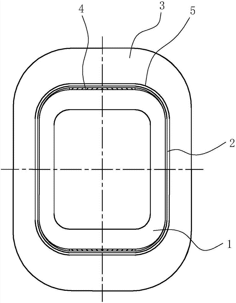
[0026] The embodiment of the present invention can be made as figure 1 The one-way transformer shown can also be made into a three-phase transformer, and the one-way transformer is taken as an example to illustrate. It includes a low-voltage coil 1, a main channel insulation 2 and a high-voltage coil 3 arranged sequentially from the inside to the outside, wherein a reinforcing material 4 is arranged between one of the adjacent layers of the last few layers of windings of the low-voltage coil. In this embodiment , the low-voltage coil 1 is a foil coil, the number of layers of the last few layers of windings of the low-voltage coil ranges from the last 2 layers to the last 5 layers, and the reinforcement material 4 is steel plate, epoxy resin plate or glass steel plate, and the reinforcement The material 4 is located at the straight line of the...


PUM


Abstract

The invention relates to an anti-short-circuit transformer coil. The anti-short-circuit transformer coil comprises a low-voltage coil and a main hollow channel insulating part and a high-voltage coil from inside to outside in sequence; the anti-short-circuit transformer coil is characterized in that a reinforcing material is arranged between at least one adjacent interlayer of the last several layers of windings of the low-voltage coil; and the outer surface of the main hollow channel insulating part and the exterior of the first winding layer are coated with a first curing material layer and a second curing material layer respectively, and are banded tightly by a first reinforced insulating material band and a second reinforced insulating material band respectively. Meanwhile, the invention also discloses a preparation method for the anti-short-circuit transformer coil; by adoption of the structure, the main hollow channel insulating distance is effectively controlled, and a condition that the main hollow channel is enlarged when a transformer is in short circuit caused by compactness of the coil windings can be avoided, so that the overall stability of the transformer coil is improved, and the anti-short-circuit capability of the transformer is improved; the preparation method is simple and efficient, and the preparation cost is close to that in the prior art, so that the large-scale production of the anti-short-circuit transformer coil can be performed conveniently; and furthermore, the anti-short-circuit capability of the transformer employing the coil is obviously better than that of the similar transformers, so that the market competitiveness of the product is reinforced to a certain degree.

Description

technical field [0001] The invention relates to the technical field of transformers, in particular to a transformer coil, and also relates to a preparation method of the transformer coil. Background technique [0002] The transformer is an important part of the power grid. It includes a core and a coil. The coil is the core part of the transformer. The coil is composed of at least two coils, a low-voltage coil and a high-voltage coil. Empty passage, the insulation provided in the main passageway is the insulation of the main passageway. When a short circuit occurs during the operation of the transformer, the high and low voltage coils of the transformer will be deformed, and the main empty channel will be greatly increased, which will affect the normal operation of the transformer, and even cause the transformer to burn out in severe cases. In order to solve the above problems, the means adopted in the prior art are usually to dip the coil in insulating varnish, and press t...

Claims


Application Information

Patent Timeline
Patent Type & Authority Patents(China)
IPC IPC(8): H01F27/28H01F27/30H01F41/061H01F41/12
CPCH01F27/2847H01F27/306H01F41/125H01F2027/2857
Inventor 王永法
Owner 王永法
Why Eureka
Try Eureka