A Circularly Polarized Slot Antenna Unit and Its Phased Array

A technology of slot antenna and circular polarization, applied in the direction of antenna, electrical components, etc., can solve the problems of application limitation, inconvenient control, complicated antenna structure, etc., and achieve the effect of high sensitivity and convenient control

Inactive Publication Date: 2018-07-27
UNIV OF ELECTRONICS SCI & TECH OF CHINA
View PDF5 Cites 0 Cited by
  • Summary
  • Abstract
  • Description
  • Claims
  • Application Information

AI Technical Summary

Problems solved by technology

However, it only performs one-dimensional beam scanning, and has not been expanded to two-dimensional level, and due to the characteristics of the microstrip antenna itself, the scanning angle of the ordinary microstrip phased array is very narrow, and this phased array is a linear pole Chemical radiation, resulting in its application is greatly limited
[0005] The literature "A Wide Band, Dual Polarized Patch Antenna for Wide Angle Scanning Phased Arrays (Doganay Dogan, 2013-4-12)" extends the scanning range of the phased array to the two-dimensional surface, but its work needs to be realized by dual-port control There are two working modes of horizontal polarization and vertical polarization, and the antenna structure is relatively complicated and inconvenient to control
[0006] Literature "A Broad Beam-width Microstrip Cross Antenna Design for Wide ScanAngle Phased Array (Zhao Wang; Dongmei Dan; Shaoqiu Xiao; Mingchun Tang. IEEE MTT-S International Microwave Workshop Series on RF and Wireless Technologies for Biomedical and Healthcare Applications, 2013-8 -13)" has improved the two-dimensional large-angle scanning phased array so that it can radiate circularly polarized waves, but each unit needs to be controlled by two ports, which reduces the overall sensitivity of the phased array

Method used


Image

  • A Circularly Polarized Slot Antenna Unit and Its Phased Array
  • A Circularly Polarized Slot Antenna Unit and Its Phased Array
  • A Circularly Polarized Slot Antenna Unit and Its Phased Array

Examples


Embodiment Construction

[0028] The present invention will be further described in detail below in conjunction with the accompanying drawings and embodiments.

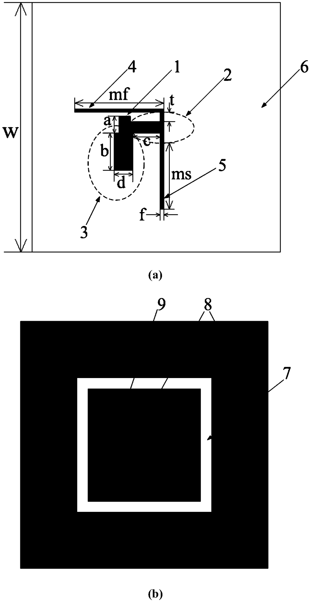
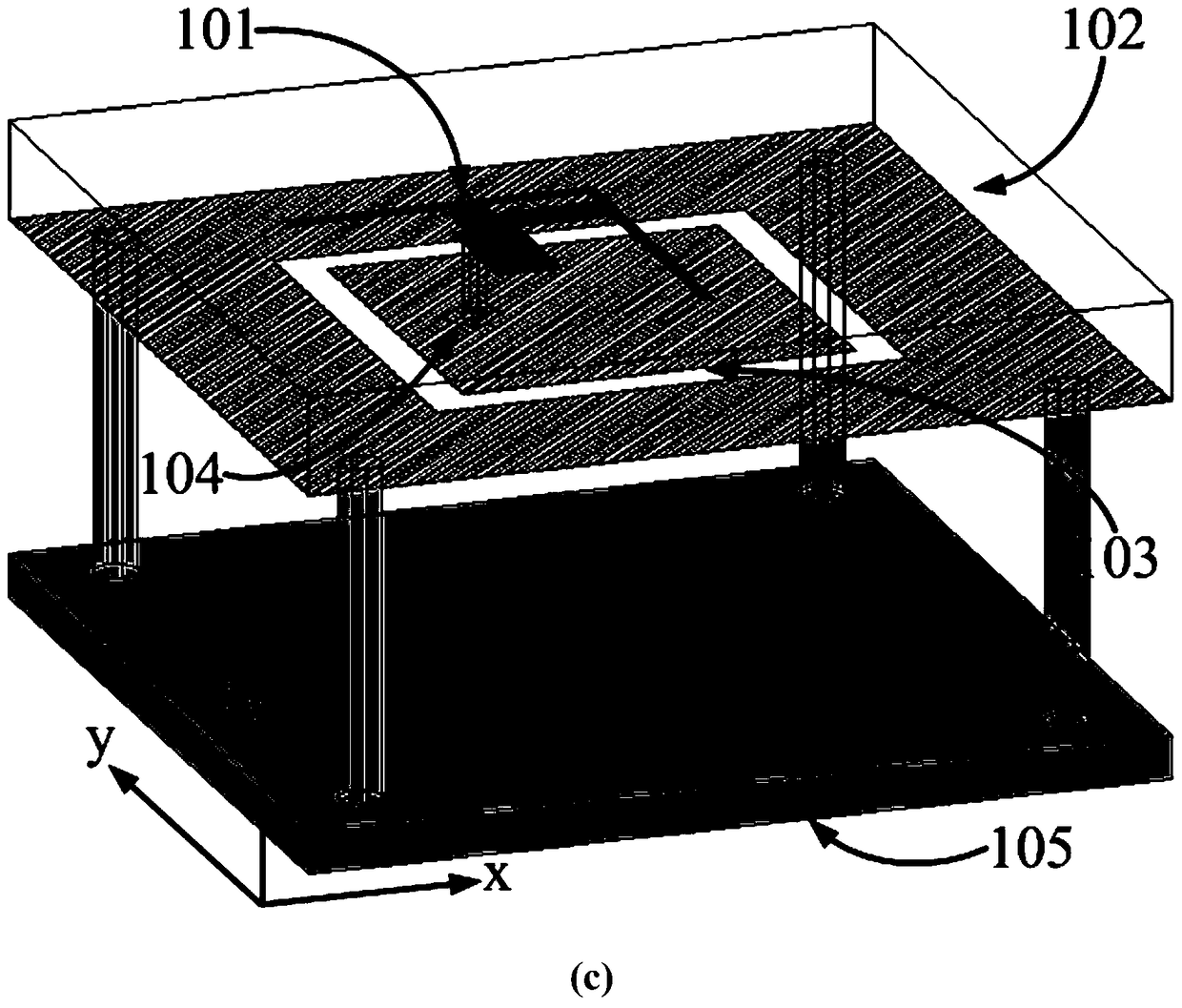
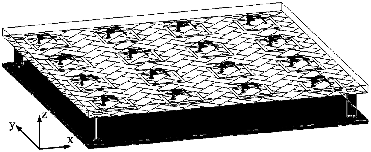
[0029] The working center frequency of the phased array antenna is 5.8GHz, and the structure of the phased array antenna unit is as follows: figure 1 (a), (b), (c), including a dielectric substrate 6, a feed patch 1, a T-shaped node 2, an open circuit matching branch 3, a first microstrip feeder 4, The second microstrip feeder 5 is arranged on the radiation slot layer on the back of the substrate and the metal reflection plate 105 under the antenna.

[0030] Such as figure 1 As shown in (a), the dielectric substrate is made of FR4 material with a dielectric constant of 4.4 and a thickness of 1mm. The feed network above the substrate is fed by the coaxial line, the characteristic impedance of the microstrip feed patch at the input end is 50 ohms, the line width is 1mm, and the length a=1.5mm, and then the energy is fed into the T-shaped secti...


PUM


Abstract

The invention discloses a two-dimensional large-angle scanning phased array based on circular polarization, which belongs to the technical field of antennas. The present invention adopts a planar microstrip structure to design a wide-beam circularly polarized antenna unit. The antenna unit includes a dielectric substrate, a feed network arranged on the front of the substrate, a square annular radiation slot arranged on the back of the substrate, and a metal reflector arranged directly below the substrate. plate. The antenna elements are properly arranged to form a phased array antenna. Finally, by controlling the feeding phase of each element, the two-dimensional large-angle scanning function of the phased array antenna is realized, and it has circular polarization characteristics.

Description

technical field [0001] The invention belongs to the technical field of antennas, and in particular relates to a phased array antenna applied in multiple aspects such as vehicle-mounted, airborne, ship-borne and space-borne radar systems. Background technique [0002] Phased array antennas are a product of the development of radar systems. The early radar system obtained a larger scanning area through mechanical rotation, while the phased array antenna changed the beam pointing of the pattern by electronically controlling the phase of the array elements, thereby covering a larger scanning area. Applying it to the radar system can greatly increase the scanning speed of the system, and provide timely information for guidance, detection, search, identification, capture and tracking, which plays a vital role in the development of the radar system. The application fields of phased array antennas are mainly reflected in the field of national defense and military affairs. In land-...

Claims


Application Information

Patent Timeline
Patent Type & Authority Patents(China)
IPC IPC(8): H01Q3/26
CPCH01Q3/2605
Inventor 丁霄裴赢洲邵维王秉中
Owner UNIV OF ELECTRONICS SCI & TECH OF CHINA
Why Eureka
Try Eureka