Power wire clamping fitting for preventing cable from loosening
A technique of loosening and clamping wires, applied in cable installation, needle tip/slotted plate contacts, electrical components used to penetrate insulated wires/cable core wires, etc., can solve the problems of poor firmness and easy loosening, etc. To achieve the effect of good anti-loosening, reasonable distribution of the center of gravity, and labor-saving operation
- Summary
- Abstract
- Description
- Claims
- Application Information
AI Technical Summary
Problems solved by technology
Method used
Image

Examples
Embodiment 1
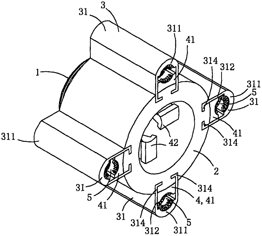
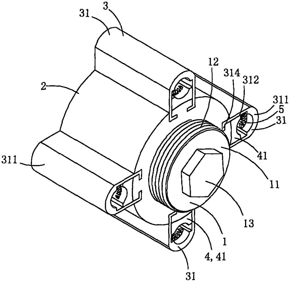
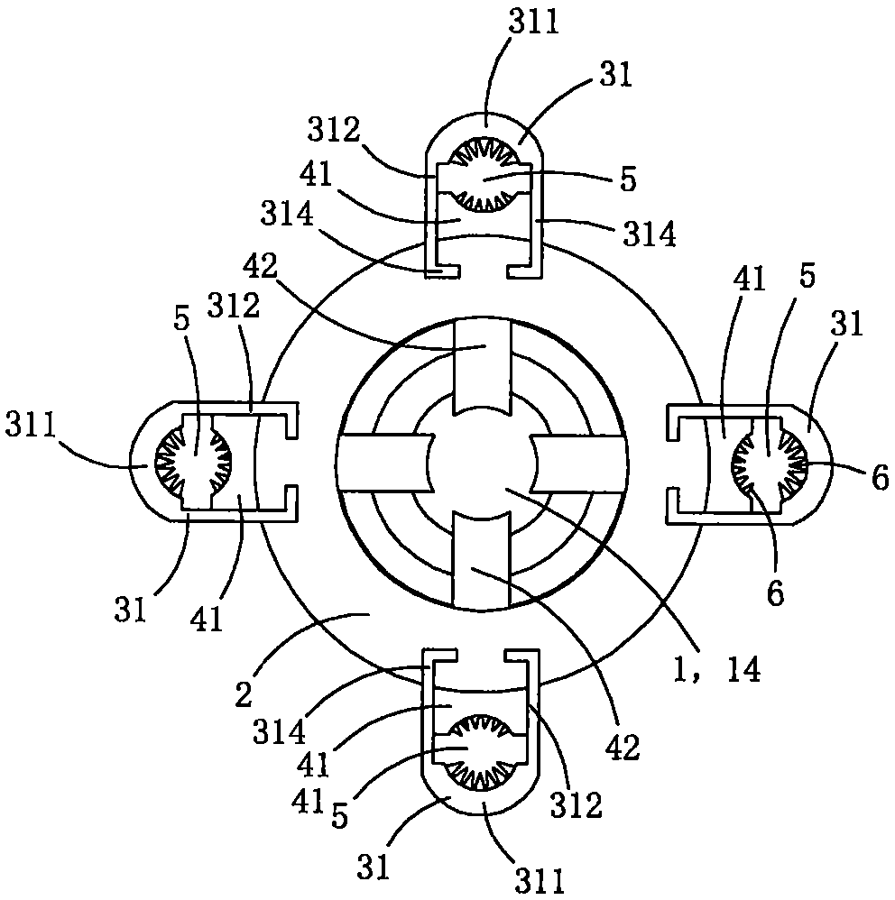
[0018] This embodiment is a kind of power clamping fittings to prevent the cable from loosening, see Figure 1 to Figure 7 As shown, it includes a jacking bolt 1 , a core tube 2 , a set of crimping assembly 3 and a set of pressing jaw assembly 8 .
[0019] The tube wall of the core tube is provided with a group of guide holes, and the group of guide holes includes four radial guide slide holes 22, and the four radial guide slide holes are evenly distributed on the core tube wall along the circumference of the core tube; The guiding sliding holes all penetrate the core tube wall along the radial direction of the core tube; each radial guiding sliding hole is located in the middle of the core tube in the axial direction, and the cross-sectional shape of each radial guiding sliding hole is I-shaped. An internal thread area 23 is provided in the lumen of the core tube.
[0020] The crimping assembly 3 includes four crimping parts 31; each crimping part is provided with a pressing...
Embodiment 2
[0035] This embodiment is basically the same as Embodiment 1, the difference is: see Figure 8As shown, this embodiment also includes a current transformer 7; the current transformer includes an annular induction body 71 and an intelligent control module 72; in this embodiment, the intelligent control module 72 is made into a ring with the same size cavity as the annular induction body The ring-shaped inductive sensing body and the intelligent control module are arranged side by side to form a ring shape, and the current transformer is sleeved and fixed on the outer wall of the pressing plate part as a whole, that is, the crimping assembly is located in the cavity of the current transformer as a whole. In practice, the current transformer can also be fixedly arranged on the tube wall of the core tube, as long as all the clamping holes are located in the cavity of the ring-shaped induction body, that is, it is only necessary to make the cable pass through the hole of the ring-sh...
Embodiment 3
[0039] This embodiment is basically the same as Embodiment 1, the difference is: see Figure 9 to Figure 10 As shown, this embodiment also includes a current transformer 7; the current transformer includes a ring-shaped induction body 71 and an intelligent control module 72; in this embodiment, the ring-shaped inductive induction body is sleeved and fixed on the outer peripheral wall of the pressing plate; the core tube Multiple accommodating cavities 73 are formed by sandwiching the outer wall, the crimping piece and the ring-shaped induction body, and the intelligent control module is arranged in the accommodating cavities. This structure can make full use of the space and is conducive to the overall small size and integration.
[0040] The intelligent control module can include a wireless transceiver unit, through which the intelligent control module transmits the leakage current signal sensed by the ring sensing body to the remote host, so as to realize precise remote unma...
PUM
 Abstract
Description
Claims
Application Information
 - R&D
- Intellectual Property
- Life Sciences
- Materials
- Tech Scout
- Unparalleled Data Quality
- Higher Quality Content
- 60% Fewer Hallucinations
Browse by: Latest US Patents, China's latest patents, Technical Efficacy Thesaurus, Application Domain, Technology Topic, Popular Technical Reports.
© 2025 PatSnap. All rights reserved.Legal|Privacy policy|Modern Slavery Act Transparency Statement|Sitemap|About US| Contact US: help@patsnap.com